Method of installing drainfield pipe

a technology of drainfield and installation method, which is applied in the direction of sewage draining, mechanical equipment, refuse collection, etc., can solve the problems of not meeting code, requiring the hole to be at the very bottom during installation, and reducing the convenience and ease of construction of such a drainfield, so as to maximize the convenience and ease of construction and minimize installation time and cost. , the effect of enhancing the ease of placement of the drainfield pip

Inactive Publication Date: 2000-09-19
DIXIE SEPTIC TANK
View PDF39 Cites 20 Cited by
  • Summary
  • Abstract
  • Description
  • Claims
  • Application Information

AI Technical Summary

Benefits of technology

In view of the foregoing background, it is therefore an object of the invention to provide a system and method for laying flexible drainfield pipe in an absorption bed or trench backfilled with aggregate such as gravel and stone. It is a primary object of the present invention to provide a method for installing flexible corrugated drainfield pipe having perforations and install such pipe such that it meets code specifications. It is further an object of the invention to provide such a method while minimizing installation time and costs while at the same time maximizing convenience and ease of the construction of such a drainfield. Another object of the invention is to enhance the ease of placement of the drainfield pipe and secure or maintain the placement to within specified code requirements during the backfilling operation. It is yet another object of the invention to provide for the easy removal of pipe installation devices after the aggregate is in place and remove the devices without displacing portions of the pipe. It is yet another object of the invention to provide a method for securing the pipe at a specified grade while clamping the pipe from a top portion thereof, thereby minimizing pipe displacement caused by portions of the device displacing aggregate proximate the pipe or contacting portions of the pipe during removal and thereby displacing the pipe. It is yet another object of the invention to provide a flexible pipe that can be used in combination with the pipe installation device whereby the combination provides an inexpensive, time saving installation method for a septic tank and drainfield comprising perforated corrugated pipe and stone or gravel styled aggregate. It is further an object of the invention to provide a device and method which facilitates the placement of the pipe within an absorption bed or trench at the specified grade for interconnected flexible pipe sections sufficient to meet the requirements of the drainfield such that a plurality of devices can be conveniently used to set the position and grade of the pipe. It i...

Problems solved by technology

When one considers the lightweight, flexible polyethylene pipe typically used in such drainfields, and the aggregate of heavy gravel, it is appreciated that holding to such dimensional code requirements is difficult, time consuming and costly.
Twisting of the pipe can cause a hole to be at the very bottom during installation.
Such a condition will not meet Code and will not pass an inspection.
It is also well known that many installations have to be reinstalled because an inspector failed the original installation because a grade or separation dimension was not met.
As stated by Houck '123, the requirements for uniformity and inspections for compliance with state and local codes makes the drainfield installation process tedious and time consuming.
As addressed in the Good '189 patent, the proper positioning of flexible pipe during the construction process has met with difficulty, since such pipe must be ma...

Method used


Image

  • Method of installing drainfield pipe
  • Method of installing drainfield pipe
  • Method of installing drainfield pipe

Examples


Embodiment Construction

The present invention will now be described more fully hereinafter with reference to the accompanying drawings, in which preferred embodiments of the invention are shown. This invention may, however, be embodied in many different forms and should not be construed as limited to the embodiments set forth herein. Rather, these embodiments are provided so that this disclosure will be thorough and complete, and will fully convey the scope of the invention to those skilled in the art. Like numbers refer to like elements throughout.

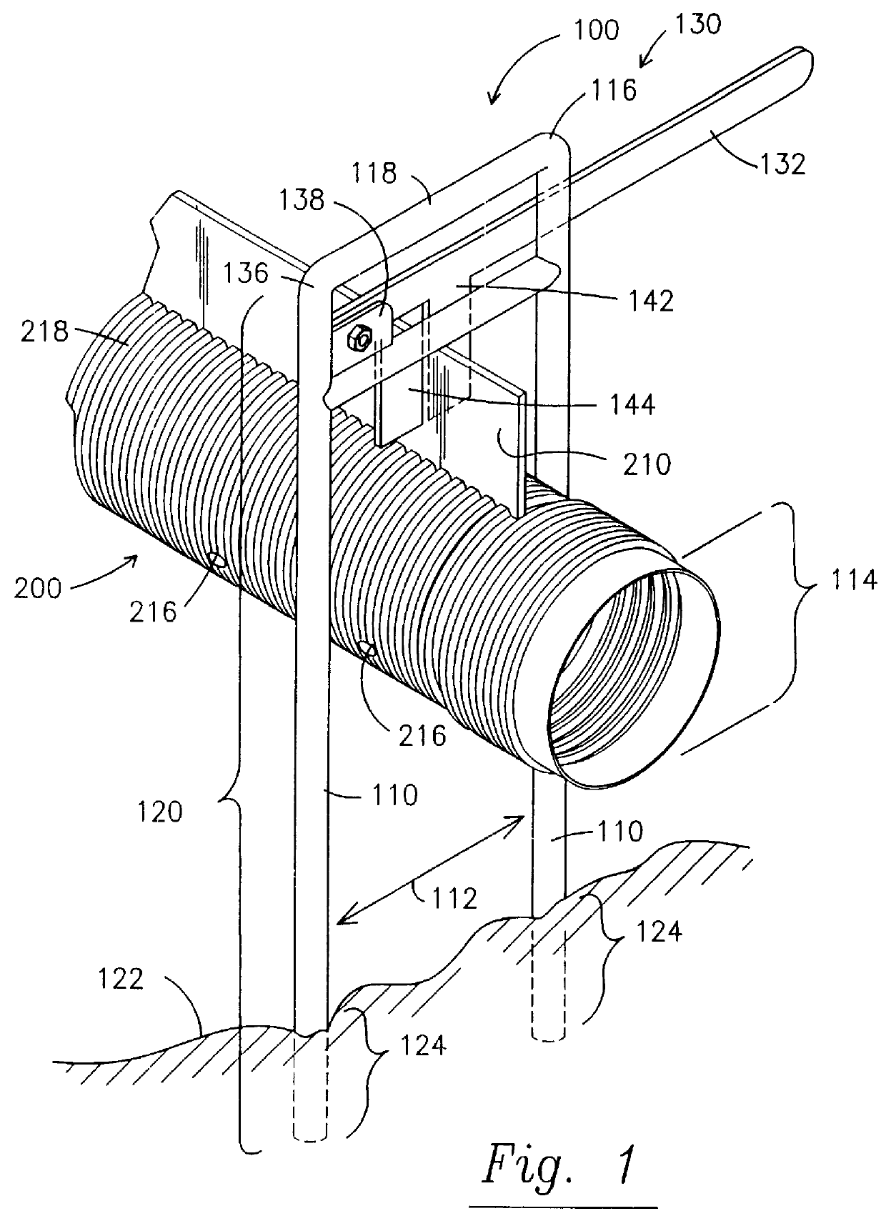
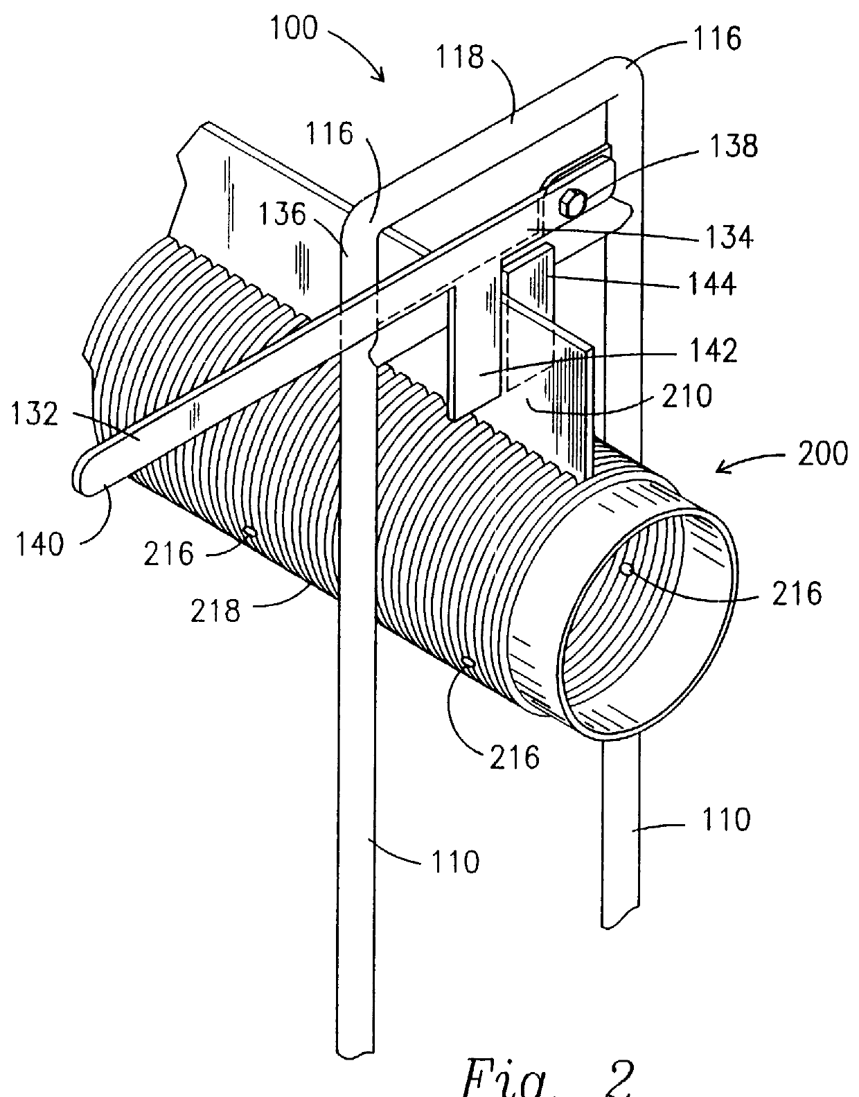
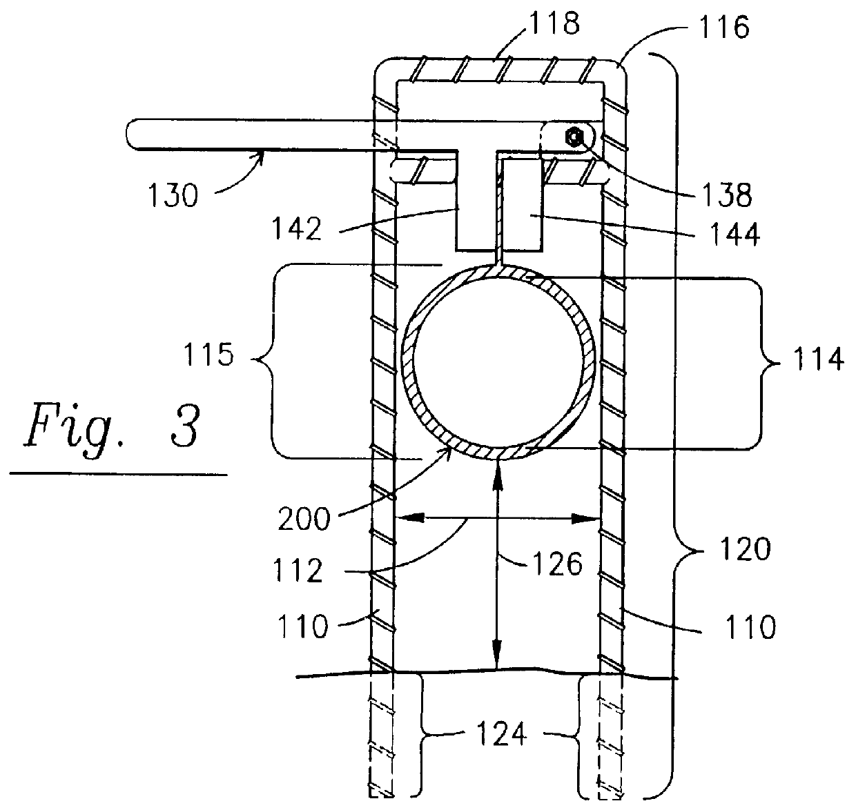
Referring now to FIGS. 1-4, a pipe supporting device 100 used in combination with a drainfield pipe section 200, in one embodiment of the present invention comprises a pair of elongated anchor members 110 generally parallel to each other and separated by a dimension 112 sufficient for receiving the pipe section 200 therebetween. Although it is anticipated that alternate uses of the present invention will be employed, the preferred embodiment is herein described ...


PUM


Abstract

A drainfield pipe having a rib radially extending from its wall is supported by a device which includes a pair of elongated anchor members generally parallel to each other and separated for receiving the drainfield pipe therebetween and suspending the pipe from its rib. The elongated anchor members penetrate a grade surface for holding the anchor members upright while supporting the pipe rib within a clamp above the grade surface. The clamp is attached to the anchor member upper portion and holds the rib between clamp jaws. Installing drainfield pipe by supporting the pipe from the radially extending rib permits the pipe to be held at desired positions for introduction of aggregate into an absorption area containing the drainfield pipe without displacing the connected pipe their desired location. With the rib positioned upward and away from the drainfield surface, the support devices holding the pipe are removed after aggregate is placed within the drainfield and around the pipe without displacing the pipe.

Description

BACKGROUND OF INVENTION1. Field of InventionThe invention relates to a method and device for the installation of on-site sewage treatment and disposal systems and in particular to drainfield installation and drainfield pipe.2. Background ArtAs defined in the Florida Administrative Code, Rule 10D-6, Department of Health and Rehabilitative Services, Standards for Onsite Sewage Treatment and Disposal Systems, onsite sewage treatment and disposal systems comprise a sewage treatment and disposal facility, that contains a standard subsurface, filled or mound drainfield system, an aerobic treatment unit, a grey water system tank, a laundry wastewater system tank, a septic tank, a grease interceptor, a dosing tank, a solids or effluent pump, waterless, incinerating or organic waste composting toilets, or a sanitary pit privy that is installed beyond a building sewer on land of the owner or on other land to which the owner has the legal right to install a system. As further defined in the ab...

Claims


Application Information

Patent Timeline
IPC IPC(8): E03F1/00E02B11/00
CPCE02B11/005E03F1/002
Inventor EVANS, KELVIN TODD
Owner DIXIE SEPTIC TANK
Why Eureka
Try Eureka