Reflow soldering device

Inactive Publication Date: 2000-09-19
PANASONIC CORP
View PDF15 Cites 29 Cited by
  • Summary
  • Abstract
  • Description
  • Claims
  • Application Information

AI Technical Summary

Benefits of technology

Also, in the reflow soldering device of the first feature of the present invention, it may be constructed such that the exhaust gas at high temperature, escaped from the heating means, is transformed to the exhaust gas of low temperature, for example 70.degree. C. and below, by the flux removing means by mixing outdoor air at room temperature into the exhaust gas, by which the liquefied or solidified component such as flux is strained and removed, whereby the device can be most simplified in its construction.
Also, in the reflow soldering device of the first feature of the present invention, it may be constructed such that the exhaust gas at high temperature escaped from the heating means, is transformed into the exhaust gas at low temperature, for example 70.degree. C. and below, by the flux removing means by mixing a gas at a temperature which is lower than the room temperature into the exhaust gas, by which the liquefied or solidified component such as flux is strained and removed, whereby the amount of the gas which is mixed in can be reduced and thereby the flux removing means can be minimized in size.
Also, in the reflow soldering device of the first feature of the present invention, it may be constructed such that the exhaust gas at high temperature, escaped from the heating means, is transformed into the exhaust gas at low temperature, for example 70.degree. C. and below, by the flux removing means by mixing a gas at a temperature which is controlled at a predetermined degree into the exhaust gas, by which the liquefied or solidified component such as flux is strained and removed, whereby the amount of the gas which is mixed in can be reduced and thereby the flux removing means can be minimized in size, and the vaporized component such as flux can be certainly removed. Furthermore, by constructing such that the temperature of the exhaust gas before and after it is strained is detected, and controlled to be kept

Problems solved by technology

However, in the above described conventional structure, as the exhaust gas passes through the duct in the factory, a vaporized component such as flux contained in the gas becomes liquid or so

Method used


Image

  • Reflow soldering device
  • Reflow soldering device
  • Reflow soldering device

Examples


Example

A first embodiment of 
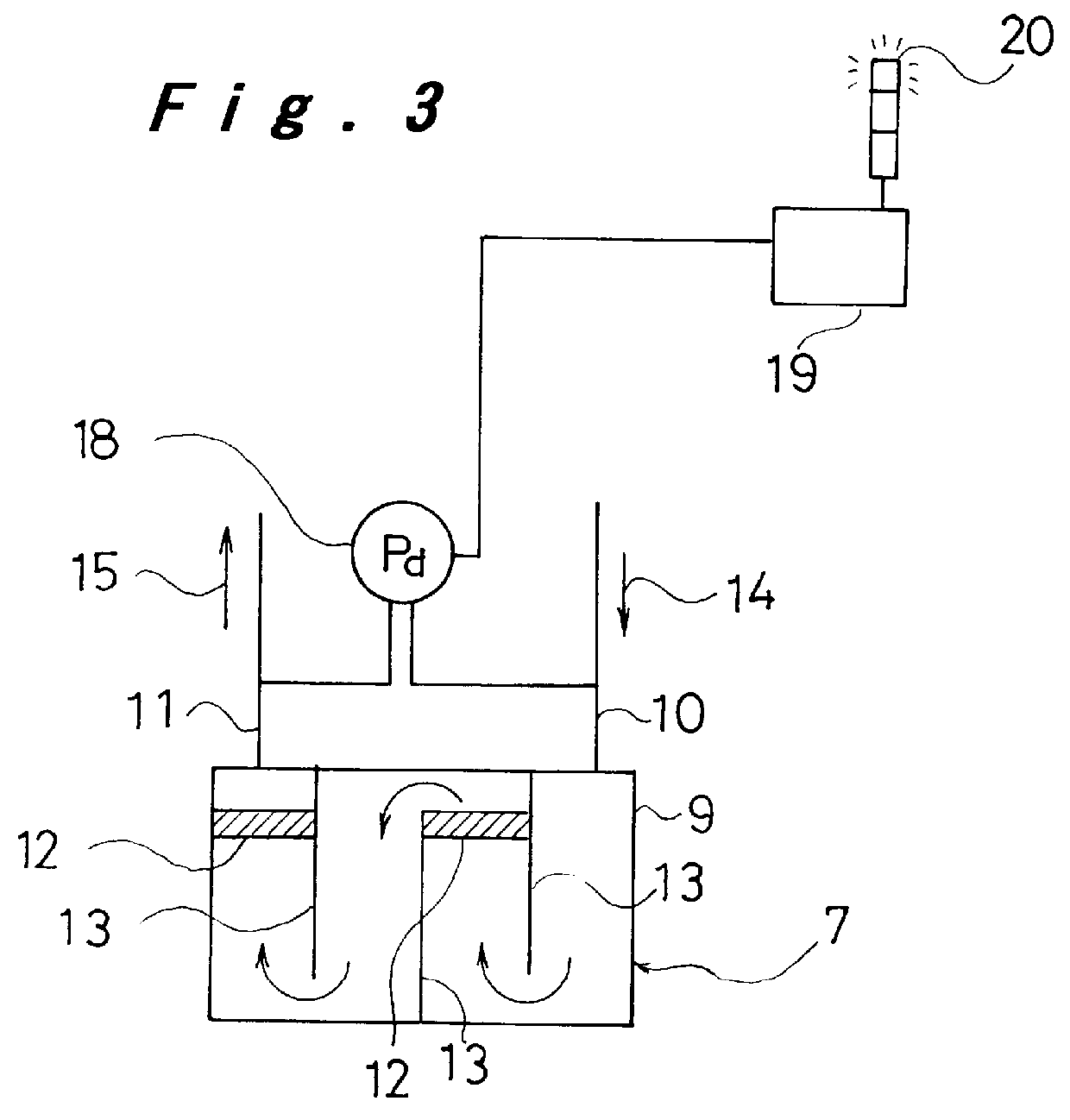
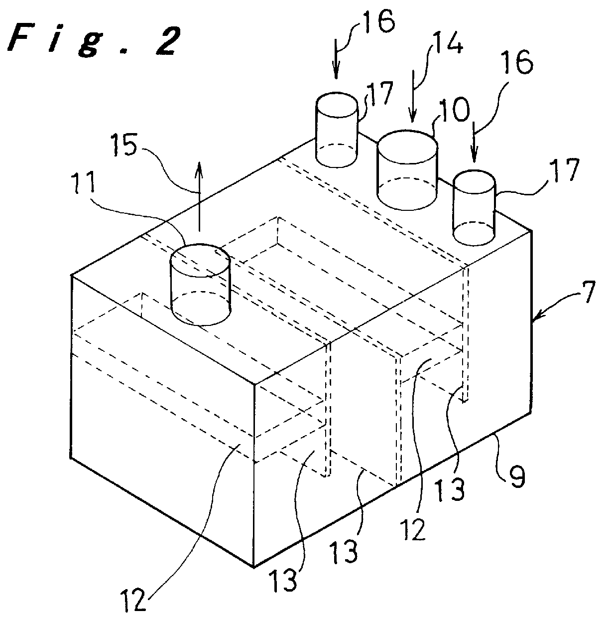
the reflow soldering device of the present invention will be explained with reference to FIG. 1 to FIG. 3. In this embodiment, the exhaust gas at high temperature is cooled down to 70.degree. C. and below by mixing a gas at room temperature as the cooling gas.

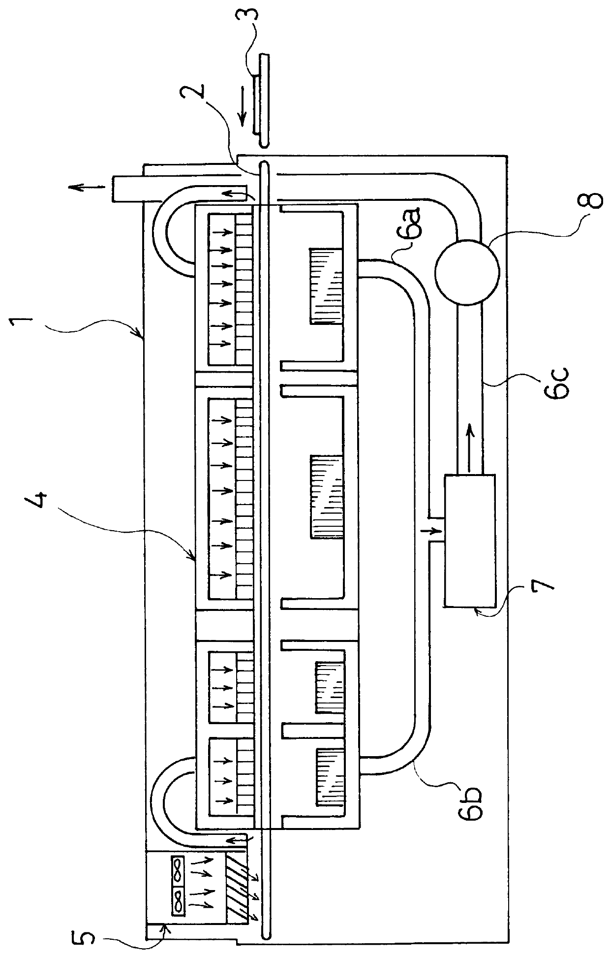
In FIG. 1, the reflows soldering device 1 of this embodiment includes a conveyor means 2 for transferring a circuit substrate 3 which is loaded in, a heating means 4 for preliminarily heating the transferred circuit substrate 3 and reflow heating the same, a cooling means 5 for cooling the reflow soldered circuit substrate 3, discharge pipes 6a, 6b, 6c for letting out a gas at high temperature discharged from the entrance and exit of the heating means 4 to the outside, a flux removing means 7 mounted in the discharge pipe 6c for removing any vaporized components such as flux contained in the exhausted gas with a built-in filter by sufficiently liquefying or solidifying the vaporized components by mixing a ...

Example

A second embodiment of the reflow soldering device will be described referring to FIG. 1 and FIGS. 4 to 6. In this embodiment, the exhaust gas at high temperature is cooled down to 70.degree. C. and below by mixing in a gas at a temperature which is lower than the room temperature as the cooling gas.

The structure of the reflow soldering device 1 of this embodiment, shown in FIG. 1, is identical to that of the first embodiment except for the flux removing means 7, and thus the description thereof with reference to FIG. 1 will be omitted.

In FIG. 4, the inside of the case 9 of the flux removing means 7 in this embodiment is similarly constructed as that of the first embodiment. It is different from the first embodiment in that cool air 16a, 16a of which temperature is controlled so as to be cooler than the room temperature is sucked into the case 9.

The cool air 16a, 16a is supplied from a temperature control blower 21 which has a built-in cooler. The temperature control blower 21 contr...

Example

A third embodiment of the reflow soldering device of the present invention will be described referring to FIG. 1 and FIG. 7. In this embodiment, the exhaust gas of high temperature is passed through a solvent, by which vaporized components such as flux are dissolved in the solvent and removed.

The structure of the reflow soldering device 1 of this embodiment shown in FIG. 1 is identical to that of the first embodiment except for the flux removing means 7, and thus the description thereof with reference to FIG. 1 will be omitted.

In FIG. 7, within the case 9 of flux removing means 7a in this embodiment, there is a tank 26 in which a solvent 27a, for example ethanol, is contained, in which the flux is soluble and which is not poisonous even if vaporized and discharged. A blower 10a is mounted at the exhaust gas intake port 10, by which the exhaust gas 14 is sucked in. The exhaust gas 14 is then blown into the solvent 27a in the tank 26 through the blowing port 10b. The vaporized compone...


PUM

PropertyMeasurementUnit
Angleaaaaaaaaaa
Temperatureaaaaaaaaaa
Pressureaaaaaaaaaa

Abstract

PCT No. PCT/JP97/01608 Sec. 371 Date Oct. 7, 1998 Sec. 102(e) Date Oct. 7, 1998 PCT Filed May 12, 1997 PCT Pub. No. WO97/43884 PCT Pub. Date Nov. 20, 1997A reflow soldering device extracts a vaporized component of a contaminative material, such as flux, from exhaust gas from a reflow furnace. The device includes a conveyor for transferring a circuit substrate, a heater for heating the transferred circuit substrate, a cooler for cooling the circuit substrate which has been reflow soldered by heater, discharge pipes and a discharge blower for discharging an exhaust gas at high temperature from the heater to the outside of the device, and a flux remover mounted in the discharge pipes which cools the exhaust gas to 70 DEG C. and below, preferably 60 DEG C. and below, so as to cause a vaporized component, such as flux contained in the exhaust gas, to become liquid or solid and to be removed.

Description

The present invention relates to a reflow soldering device for mounting an electronic component on a circuit substrate by soldering.One example of conventional reflow soldering device will be explained with reference to FIG. 11.In FIG. 11, the conventional reflow soldering device 1 includes a conveyor means 2 for transferring a circuit substrate 3 which is loaded in, a heating means 4 for preliminarily heating the transferred circuit substrate 3 and reflow heating the same, a cooling means 5 for cooling the reflow soldered circuit substrate 3, discharge pipes 6a, 6b, 6c for letting out a gas of high temperature escaped from the entrance and exit of the heating means 4 to the outside, and a discharge blower 8 mounted in the discharge pipe 6c.Exhaust gas from the discharge pipes 6a, 6b, 6c is discharged to the outside through a duct in the factory.However, in the above described conventional structure, as the exhaust gas passes through the duct in the factory, a vaporized component su...

Claims


Application Information

Patent Timeline
IPC IPC(8): B23K1/012B01D46/42B01D53/34H05K3/34
CPCB23K1/012
Inventor INOMATA, AKIONONOMURA, MASARUMASUI, MASUOCHIKAHISA, NAOICHI
Owner PANASONIC CORP
Why Eureka
Try Eureka