Automated saw for splitting carcasses

a saw and automatic technology, applied in the field of automatic saws, can solve the problems of inconvenient processing, inconvenient cutting, slow speed, etc., and achieve the effect of higher speed

Inactive Publication Date: 2000-10-03
JARVIS PROD
View PDF9 Cites 35 Cited by
  • Summary
  • Abstract
  • Description
  • Claims
  • Application Information

AI Technical Summary

Benefits of technology

is to provide an automated saw which can operate at higher speeds than prior art designs to accommodate maximum carcass rail speeds.
Another feature of the invention is an automatic safety brake connected between the first vertical carriage and the splitting station frame. The safety brake prevents the vertical carriage from dropping rapidly in the event of a power failure.
It is desired for the back roller assembly to include at least two back rollers that are approximately conical over a portion thereof to help guide the carcass into position during cutting. The most highly preferred design uses at least four back rollers mounted in a pivoting bracket, the bracket pivoting to allow the back rollers to continuously contact the carcass as the carcass is split. Smaller back rollers may also be used in conjunction with the larger conical back rollers to better position the back of the carcass.

Problems solved by technology

Automated saws for accomplishing this task are known, but they suffer from various problems, including inaccurate cutting and slow speed.
Inaccurate cutting is objectionable as it wastes valuable meat and makes subsequent processing more difficult.
Slow speed limits the rate at which carcasses can be processed, or requires that multiple splitting machines be installed to process multiple carcasses simultaneously.
One problem with this design is that the carcass is not accurately held relative to the saw by the guide plates due to variations in the size and shape of the carcass.
This inaccurate cutting relative to the center line of the backbone is objectionable to the meat processing industry.
A second difficulty relates to the weight of the U-frame due to the need to maintain accurate alignment between the opposite vertical legs of the frame while supporting the carcass from the back and driving the saw vertically along the opposite leg of the frame.
The lower horizontal elements of the U-frame, needed to connect and rigidly support the two vertical legs of the frame in the correct relationship, tend to be heavy.
Because the entire U-shaped frame must be returned to the starting point as soon as a cut has been completed, excess weight adversely affects the return speed of the saw.
Unfortunately, in this design the saw begins to cut before the rollers achieve good contact with the carcass.
Any initial misalignment as the saw begins to cut results in at least a portion of the carcass being cut improperly off the center line of the backbone.
Such initial misalignment is difficult to avoid when the cut is started before the rollers have properly aligned the carcass.
A related problem with this design is speed.
This extension and positioning of the arm and rollers between the legs of the carcass is time consuming and slows the cutting operation significantly.
There is yet another problem that arises from the mounting of the guide rollers on the same arm carrying the saw.
In the design described above, it is not possible for the saw to be retracted relative to the carcass (as needed to make a partial cut) without also partially retracting the roller mounted on the same arm.
Thus, if it is desired to make a partial cut, the carcass cannot be held accurately in position relative to the saw.
Another speed problem for the above design arises from the necessity of lifting the back roller and supporting arm sufficiently high to pass between the legs of the carcass.
Moving any additional distance beyond the minimum needed to position the saw at the top of its cutting point takes additional time and slows processing.
The necessity to pass the back rollers between the legs of the carcass also places various other objectionable limitations on the size, shape and rigidity of the arm which limits accurate positioning of the saw relative to the carcass.

Method used


Image

  • Automated saw for splitting carcasses
  • Automated saw for splitting carcasses
  • Automated saw for splitting carcasses

Examples


Embodiment Construction

)

In describing the preferred embodiment of the present invention, reference will be made herein to FIGS. 1-22 of the drawings in which like numbers refer to like features of the invention.

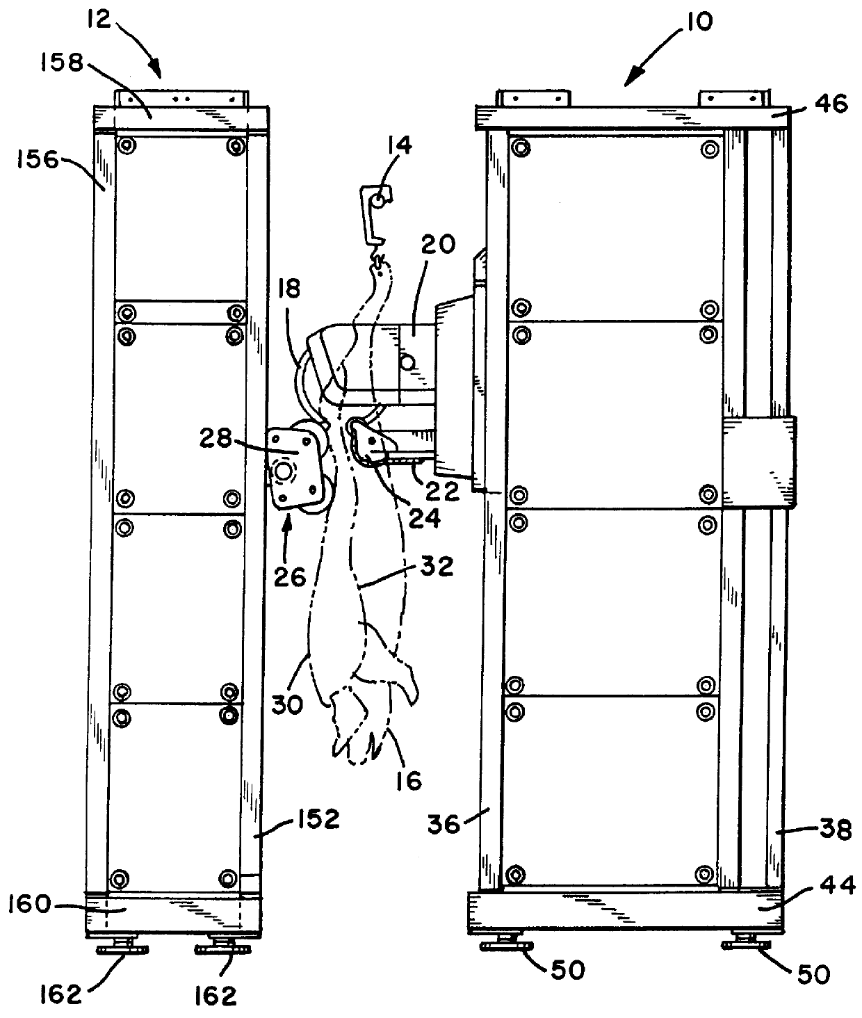
Referring to FIG. 1, the invention generally comprises a splitting station 10 and a back roller station 12 located on opposite sides of a carcass rail 14. Carcasses 16 are suspended by their hind feet from trolleys carried on the carcass rail 14, and the carcasses are continuously driven between the splitting station 10 and back roller station 12 where they are split by saw 18.

The carcass is first positioned by extending the guide roller assembly 24 from the splitting station 10 and the back roller assembly 28 from the back roller station 12. The saw 18 is then extended and the cut is made vertically as the saw, guide rollers and back rollers all track the moving carcass. The rollers and saw are then retracted and repositioned to cut the next carcass.

To achieve this operation, the saw 18 is movable...


PUM


Abstract

An automated saw for high speed splitting of suspended carcasses, such as hog carcasses, through the backbone as the carcasses continuously move along a carcass rail includes a splitting station and a back roller station located on opposite sides of the carcass rail. The splitting station includes a splitting saw that can be driven in three directions, including horizontally towards a carcass to begin cutting, vertically down to make the cut and horizontally parallel to the carcass rail to match the speed of the moving carcass as the cut is made. A guide roller carried by the splitting station positions the backbone in a known position relative to the saw. The back roller station includes a back roller for positioning the carcass relative to the saw as the cut is made. The back roller is also movable in three directions, including horizontally in to contact the carcass, vertically down, and horizontally parallel to the carcass rail to match the motion of the saw. The back roller and saw are structurally independent, but are accurately driven to maintain the relative position of the saw and the back roller as the cut is made.

Description

1. Field of the InventionThe present invention relates to saws for splitting eviscerated carcasses while the carcass is suspended and continuously moving along a carcass rail. More specifically, the invention relates to automated saws that split the carcass vertically by simultaneously driving the splitting saw vertically to make the cut and horizontally to follow the moving carcass.2. Description of Related ArtOne step in the processing of carcasses, particularly hog carcasses, is to split the carcass after it has been eviscerated. Automated saws for accomplishing this task are known, but they suffer from various problems, including inaccurate cutting and slow speed. Inaccurate cutting is objectionable as it wastes valuable meat and makes subsequent processing more difficult. Slow speed limits the rate at which carcasses can be processed, or requires that multiple splitting machines be installed to process multiple carcasses simultaneously.U.S. Pat. No. 4,653,150 issued to Leining ...

Claims


Application Information

Patent Timeline
Patent Type & Authority Patents(United States)
IPC IPC(8): A22B5/20A22B5/00A22C17/06A22C17/02
CPCA22B5/202A22B5/20
Inventor KIELWASSER, DECEASED, JEAN C.
Owner JARVIS PROD
Why Eureka
Try Eureka