Brushless three-phase synchronous generator having enhanced rotor field system

a synchronous generator and enhanced rotor field technology, applied in the direction of synchronous generators, electric generator control, dynamo-electric machines, etc., can solve the problems of lowering the generator efficiency and the likelihood of excessive output voltag

Inactive Publication Date: 2000-10-10
SATAKE CORP
View PDF5 Cites 10 Cited by
  • Summary
  • Abstract
  • Description
  • Claims
  • Application Information

AI Technical Summary

Problems solved by technology

Since the field windings are wound on the periphery of the rotor with evenly distributed, some of the field windings do not effectively produce the field magnetic flux, resulting in lowering of the g...

Method used


Image

  • Brushless three-phase synchronous generator having enhanced rotor field system
  • Brushless three-phase synchronous generator having enhanced rotor field system
  • Brushless three-phase synchronous generator having enhanced rotor field system

Examples


first embodiment

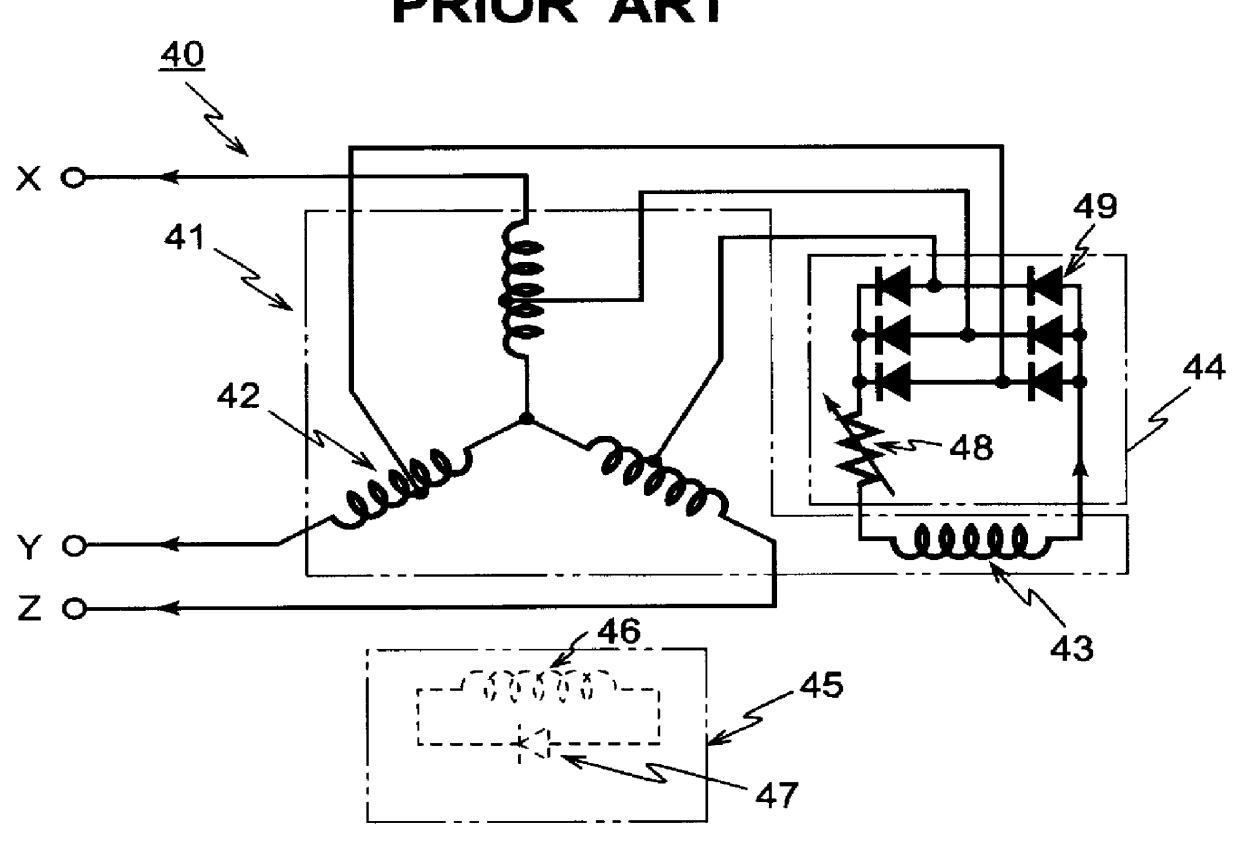
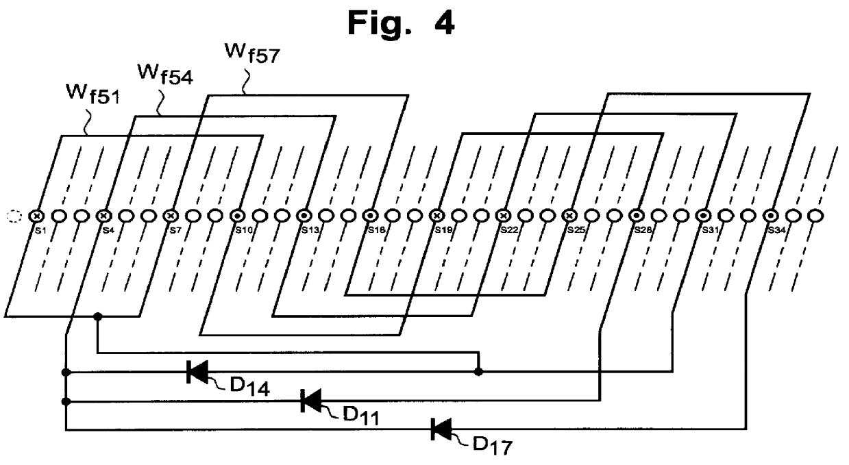
FIGS. 3, 4, 5 and 6 show the brushless three-phase synchronous generator 70 according to the invention. FIG. 3 shows a circuit diagram of the generator 70 according to the invention. As noted from FIG. 3, the difference of the generator 70 of the present invention from the conventional one 40 shown in FIG. 1 resides only at the rotor side 60. FIG. 4 shows a circuit diagram of one set, among three sets in total, of the field windings of the rotor. FIG. 5 is a further detailed diagram showing the connection of the three sets of the plurality of rotor windings W.sub.f51 -W.sub.f59. FIG. 6 shows a graph showing the currents in the field windings of the generator according to the present invention and those of the conventional generator.

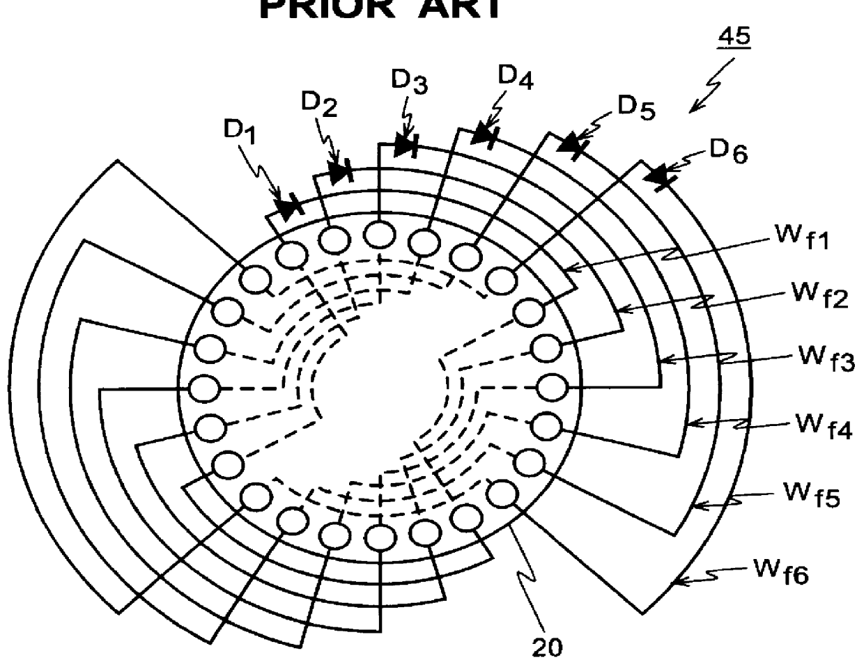
The stator side 41 of the generator 70 according to the present invention is the same as that of the conventional one. Specifically, the stator 41 comprises primary generating windings 42 of three-phase four-pole, stator excitation windings 43 whose numbe...

second embodiment

Next, FIG. 7 shows the field winding circuit according to the present invention. In this embodiment, the field windings W.sub.f51 and W.sub.f57 in which the same phase voltages are induced therein are firstly directly connected in parallel so that an AC component loop circuit 80 is formed and, then, they are connected in parallel to the central field windings W.sub.f54 through a diode D20. In this embodiment, it should be noted that a plurality of the field windings of the same phase which are directly connected in parallel are further connected in parallel to the central field windings through at least one common diode D20. With the provision of the AC component loop circuit 80 in this embodiment, there flows a circulating current between the field windings concerned since the phase difference of currents flowing therein based on the fundamental wave component of the opposite-phase rotating magnetic field in the case where the single-phase load is connected to the generator, become...

third embodiment

FIG. 8 shows the field winding circuit according to the present invention. In this embodiment, among the plurality of field windings W.sub.f51 -W.sub.f59 of the full-pitch concentrated winding type, the field windings W.sub.f52 and W.sub.f59 in which the voltages of the same phase are induced but the above phase is different in predetermined degrees from the phase of the voltage induced in the central field windings W.sub.f54 by the odd-order spatial higher harmonic magnetic fields, are connected in parallel through the corresponding diodes D12, D14. The parallel-connected field windings W.sub.f52 and W.sub.f59 are further connected in parallel to the central field windings W.sub.f54 to which a circulating diode D14 is connected.

According to the above circuit constructions, as is the same in the above-explained first embodiment, the current to flow in the central field windings W.sub.f54 increases and further its waveforms are greatly smoothed. There are some cases where, when load ...


PUM


Abstract

A brushless three-phase synchronous generator includes a stator having primary generating windings and stator excitation windings whose number of poles is odd-number times the number of poles of the primary generating windings. The generator further includes a cylindrical rotor on which a plurality of field windings are wound in a full-pitch concentrated winding form. The plurality of field windings are respectively short-circuited by the corresponding diodes. A plurality of field windings in which voltages of the same phase are induced based on the odd-order spatial higher harmonic magnetic fields are connected in parallel and further connected in parallel to the central field windings which effectively produce primary field magnetic fluxes. A circulating rectifier element is connected in parallel to the central field windings. Improvement in the waveforms of the primary magnetic fields can be achieved and self-excitation in the case where the single-phase loads are connected can be prevented from occurring while magnetic coupling of the rotor field windings to the spatial higher harmonic components of the armature reaction magnetic fields is effectively maintained well.

Description

(1) Field of the InventionThe present invention relates to a brushless three-phase synchronous generator. More particularly, the present invention relates to a circuit construction of the rotor field windings for use in the brushless three-phase synchronous generator, which is so devised that an improvement is made on waveform of the current flowing in the rotor field windings induced based on the odd-order higher harmonic magnetic fluxes generated by the stator excitation windings and that an enhancement is achieved on the excitation efficiency.(2) Description of the Related ArtFirst, a conventional brushless three-phase synchronous generator is explained with reference to FIGS. 1 and 2. FIG. 1 shows a circuit diagram of the conventional brushless three-phase synchronous generator 40. At a stator side 41, there are provided three-phase four-pole primary generating windings 42, stator excitation windings 43 whose number of poles is 12, odd-number times the number of poles of the pri...

Claims


Application Information

Patent Timeline
IPC IPC(8): H02K19/28H02K19/16
CPCH02K19/28
Inventor SATAKE, SATORUONOGI, YUKIOINOUE, KENJIMATSUDA, MASANORI
Owner SATAKE CORP
Why Eureka
Try Eureka