Voltage regulator with wide control bandwidth

a voltage regulator and control bandwidth technology, applied in the direction of electric variable regulation, process and machine control, instruments, etc., can solve the problems of inefficiency in meeting these requirements, art is respectively too slow or inefficient in meeting these requirements

Inactive Publication Date: 2000-10-10
SEMTECH CORP
View PDF4 Cites 68 Cited by
  • Summary
  • Abstract
  • Description
  • Claims
  • Application Information

AI Technical Summary

Problems solved by technology

As the number of transistors employed in an integrated circuit increases, particularly for example in a microprocessor, the requirements for supplying power to the integrated circuit have become more demanding.
Traditional linear and conventional switched regulators well known to those of ordinary skill in the art are respectively too inefficient in meeting these requirements or too slow to meet these requirements.
Though the linear power supply has a fast response time, it is not very efficient.
As such, it is it is not a realistic approach to proving power in many integrated circuit applications.
However, there is limitation on how quickly a switching converter can provide current to readily changing load condition.
This approach is not that efficient because current continuously flows through the linear regulator.
In both the Pizzi et al. and Harris Semiconductor approaches, there is lack of a control mechanism to force the switch regulator current to equal the load current.
This can be a problem because it requires matching two independently set reference voltages.
Further, in microprocessor application, tight voltage band tolerance may not be feasible because for some static regulation errors bigger transient voltage spikes are permitted.

Method used


Image

  • Voltage regulator with wide control bandwidth
  • Voltage regulator with wide control bandwidth
  • Voltage regulator with wide control bandwidth

Examples


Embodiment Construction

Those of ordinary skill in the art will realize that the following description of the present invention is illustrative only and not in any way limiting. Other embodiments of the invention will readily suggest themselves to such skilled persons.

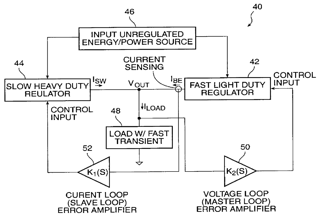
In FIG. 3, a block diagram of the voltage regulator 40 according to the present invention is illustrated. In the voltage regulator 40, a fast light duty regulator 42 and a slow heavy duty regulator 44 are coupled in a master-slave topology. The unregulated input 46 to the voltage regulator 40 is coupled to both the light duty regulator 42 and the heavy duty regulator 44. The output, Vout, of the voltage regulator 40 is coupled to the load 48 and also to the outputs of both the light duty regulator 42 and the heavy duty regulator 44. The master loop includes an error amplifier 50 having an input coupled to Vout, and an output coupled to a control input of the light duty regulator 42. The slave loop includes an error amplifier 52 having an inpu...


PUM


Abstract

A fast buffer and switching regulator are combined in parallel in a master-slave loop topology to form a voltage regulator. The buffer circuit has a voltage sensing amplifier that senses the difference between the voltage at the output of the voltage regulator and a reference voltage. This voltage difference is amplified, and then input to a buffer that sources current to or sinks current from the output of the voltage regulator. The output of the buffer circuit is coupled to the switching converter which senses the changing buffer circuit output current. The switching converter changes its duty cycle to oppose the current from the buffer circuit. This is a master-slave loop topology wherein the buffer circuit is the master loop that quickly provides high levels of current to compensate for a voltage transient at the output of the voltage regulator, and the switching converter is the slave loop which eventually takes over from the master loop to meet the current output requirements of the voltage regulator.

Description

1. Field of the InventionThe present invention relates to voltage regulators. More particularly, the present invention relates to voltage regulator that employs a switching circuit having a pulse width modulator controlled by a high speed buffer circuit employed in a master-slave topology for fast response to rapidly changing load current.2. The Prior ArtAs the number of transistors employed in an integrated circuit increases, particularly for example in a microprocessor, the requirements for supplying power to the integrated circuit have become more demanding. It is presently contemplated that as the Vcc in a microprocessor drops to approximately 1 to 1.5 volts, the current required by the microprocessor will be in a range of about 35 to about 50 amps. Accordingly, the power dissipation in the microprocessor will be at least 50 watts.To conserve power in a multitude of applications, such as a notebook computer, the microprocessor will switch into a sleep mode, as is presently under...

Claims


Application Information

Patent Timeline
Patent Type & Authority Patents(United States)
IPC IPC(8): G05F1/575G05F1/10
CPCG05F1/575
Inventor YANG, ERIC X.BURGYAN, LAJOSBHURJI, PRABHJYOT S.
Owner SEMTECH CORP
Why Eureka
Try Eureka