Lock assembly

a technology of lock and assembly, applied in the field of door locks, can solve the problems of door unlocking and opening, door to open sufficiently, etc., and achieve the effect of increasing the lock engagement for

Inactive Publication Date: 2000-10-31
WESTINGHOUSE AIR BRAKE CO
View PDF13 Cites 75 Cited by
  • Summary
  • Abstract
  • Description
  • Claims
  • Application Information

AI Technical Summary

Benefits of technology

It is also an object of the present invention to provide a transit vehicle door loc

Problems solved by technology

These doors must function in a hostile environment which at least includes heavy usage, relatively large temperature extremes, vibration loads, acceleration loads and spurious electrical signals.
Such spurious electrical signals may be caused by lightning, by interrupted contact with a third rail, and/or strong radio signals.
No credible failure mode should cause a door to open sufficiently for a

Method used


Image

  • Lock assembly
  • Lock assembly
  • Lock assembly

Examples


Embodiment Construction

, particularly, when the detailed description is taken in conjunction with the attached drawing figures and with the appended claims.

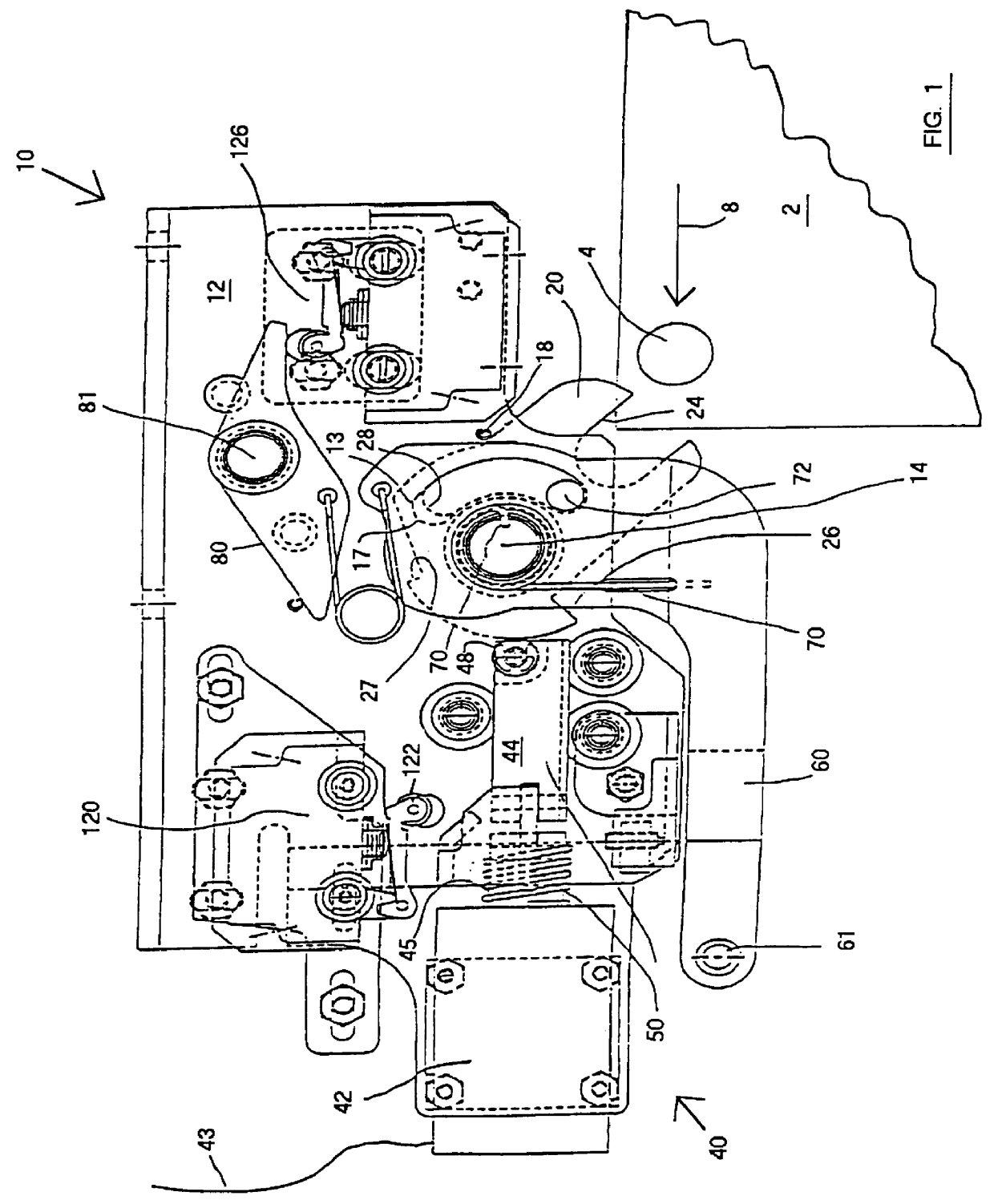
FIG. 1 is a schematic front elevation view of a presently preferred embodiment of the inventive door lock in an unlocked position with the door open and moving toward the closed position;

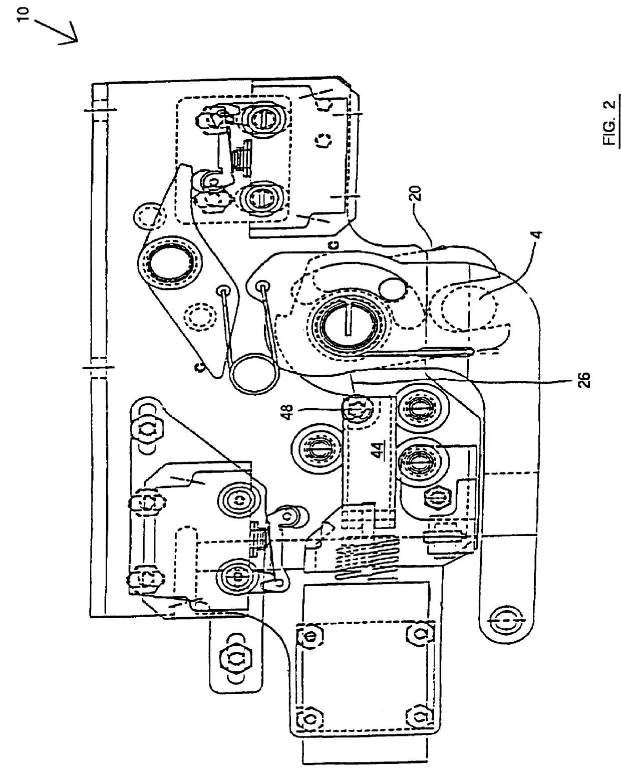
FIG. 2 is a schematic front elevation view of the door lock illustrated in FIG. 1 showing the lock cam engaging the door lock element on the door as the door is being locked;

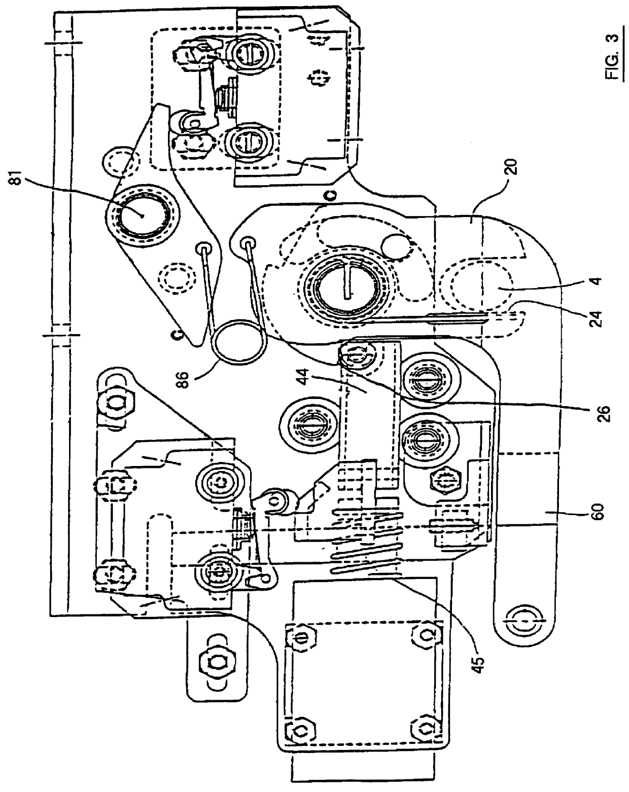
FIG. 3 is a schematic front elevation view of the door lock illustrated in FIG. 1 in the locking position;

FIG. 4 is a schematic front elevation view which illustrates an undercut angle on the lock cam so that when the door is locked any force tending to open the door will increase the locking forces;

FIG. 5 is a schematic front elevation view showing the door lock illustrated in FIG. 1 when the lock actuator is energized to unlock the door;

FIG. 6 is a schematic front elevation view which illustrates...


PUM


Abstract

A door lock for locking a sliding door on a transit vehicle. The lock has a base for attachment to the transit vehicle and a lock cam having a slot for engaging a door lock element attached to the door. A pivot is connected to the base and to the lock cam to provide a rotary connection of the lock cam to the base. A lock actuator is attached to the base. The lock actuator includes a moveable actuator portion for engaging the lock cam to prevent rotation of the lock cam to lock the door. The actuator also has an energized actuator portion for withdrawing the moveable actuator portion from engagement with the lock cam to release the lock cam and unlock the door. The energized actuator portion is connectable with a control system for the transit vehicle door. The lock also has a manual release mounted to engage the moveable actuator portion to move it from engagement with the lock cam to release the lock cam and hence unlock the door. A sprag engaged with the manual release prevents locking of the door after the manual release has been used.

Description

The present invention relates, in general, to door locks for passenger transit vehicle type doors and, more particularly, this invention relates to door locks for sliding doors utilized in a passenger transit vehicle.The design and construction of passenger transit vehicle doors is crucial for the safety of the travelling public. These doors must function in a hostile environment which at least includes heavy usage, relatively large temperature extremes, vibration loads, acceleration loads and spurious electrical signals. Such spurious electrical signals may be caused by lightning, by interrupted contact with a third rail, and / or strong radio signals. They must function reliably for a very large number of cycles. For many applications, they must be designed to function rapidly and safely without the direct observation thereof by an operator of the transit vehicle.The doors should have locks so that they cannot be opened by application of opening forces to the doors when the doors ar...

Claims


Application Information

Patent Timeline
IPC IPC(8): E05B65/12E05B65/08E05B63/18E05B63/00
CPCE05B83/42E05B83/40E05B81/14E05B63/0069E05B63/18E05B65/0811Y10S292/65Y10T292/1048Y10T292/1082
Inventor HEFFNER, STEVEN P.GOLEMIS, FOTIOS
Owner WESTINGHOUSE AIR BRAKE CO
Why Eureka
Try Eureka