Magnetically actuated float switch

a float switch and magnet technology, applied in liquid/fluent solid measurement, machines/engines, instruments, etc., can solve the problems of more prone to failure to activate and deactivate purely repelling magnetic arrangements, and achieve uniform and consistent force, more reliably activate and deactivate

Inactive Publication Date: 2000-10-31
S J ELECTRO SYST INC
View PDF3 Cites 27 Cited by
  • Summary
  • Abstract
  • Description
  • Claims
  • Application Information

AI Technical Summary

Benefits of technology

With the above mentioned shortcomings and inventive goals in mind, the present invention provides for a magnetically actuated float switch for turning on and off an electrical load device which utilizes both an attracting force and a repelling force, which cumulatively provide the force necessary to actuate the switch. Purely repelling magnetic arrangements are more prone to fail to activate. Purely attracting magnetic arrangements are more prone to fail to deactivate. By utilizing both repelling and attracting magnetic forces, applicants have provided a switch which is more uniform and consistent, so that the system can be tuned or configured to more reliably activate and deactivate as compared to the prior art. This is done with a bracket having magnetic ends which are arranged in a repelling arrangement. A float rod magnet is carried by a float rod which is arranged so that it moves vertically upwardly and downwardly, such that when the liquid rises over a predetermined level, the float rod magnet will magnetically interact with the two magnetic ends of the bracket, the float rod magnet being repelled by one end and attracted by the other, so that a more uniform and consistent force is created which causes the switching action. As the float rod magnet is rising, it will initially be repelled downward by the closest magnetic end of the bracket. This creates a translational resistance which provides an e

Problems solved by technology

Purely repelling magnetic arrangements are more prone to fail to activate.
P

Method used


Image

  • Magnetically actuated float switch
  • Magnetically actuated float switch
  • Magnetically actuated float switch

Examples


Embodiment Construction

is hereafter described with specific reference being made to the drawings in which:

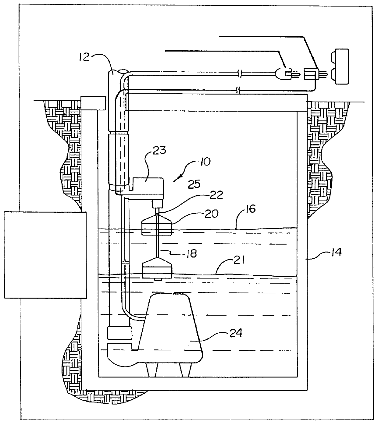
FIG. 1 is a side perspective view of the inventive magnetically actuated float pump in a pump-down sump pump application;

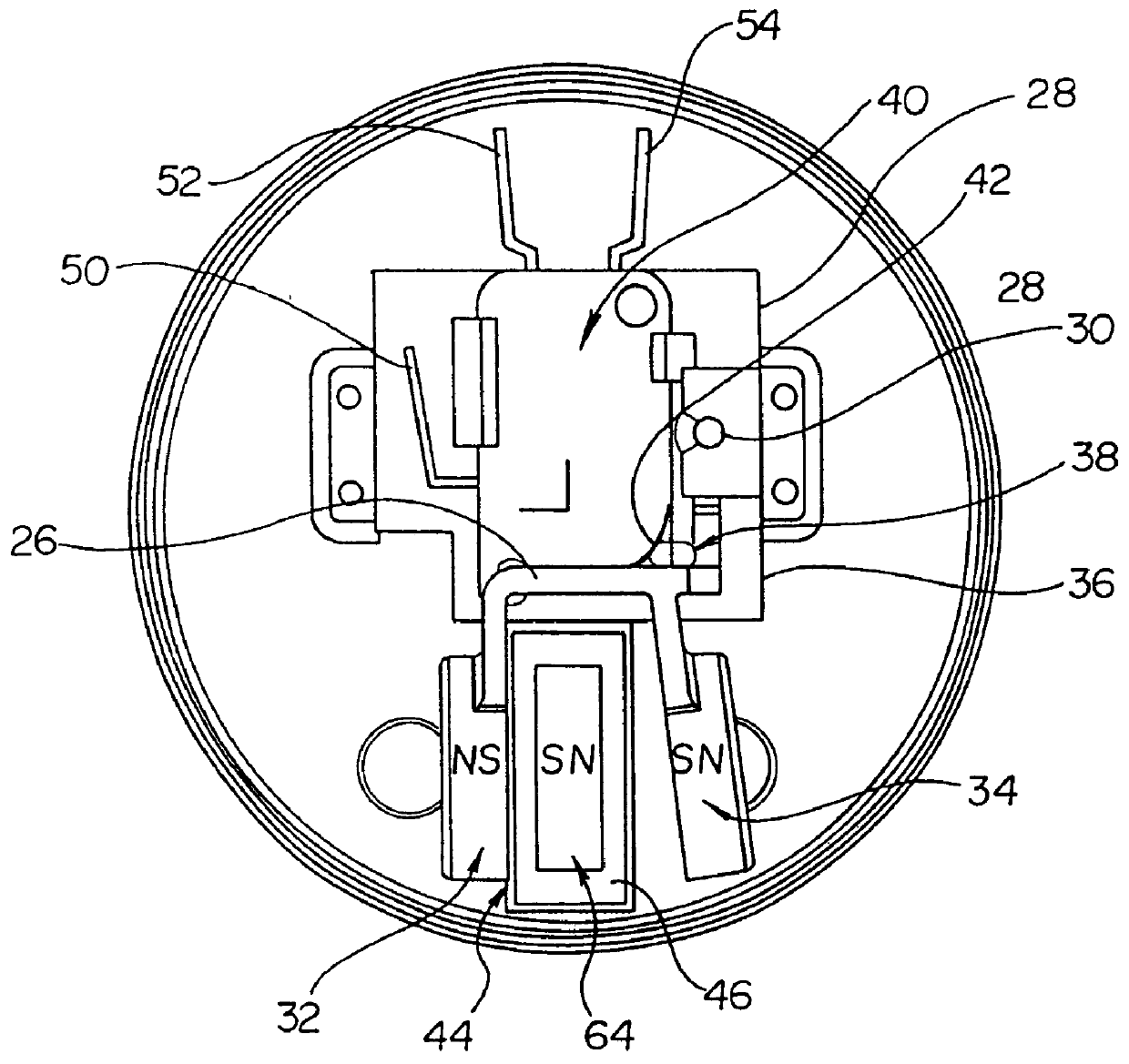
FIG. 2 is a top view of the inventive float switch showing the bracket in its first or open position;

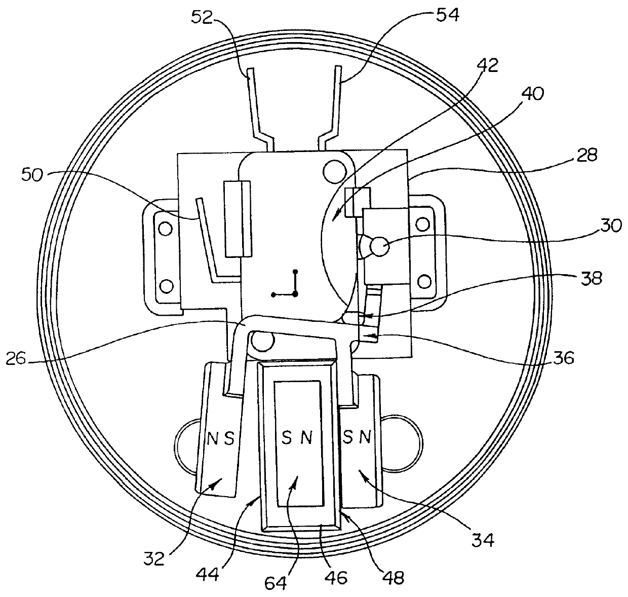
FIG. 3 is a top view of the inventive float switch showing the bracket in its second or closed position;

FIG. 4 is perspective view of the inventive float switch;

FIG. 5 is a perspective view of the switch internal mechanism;

FIG. 6 is a top view of the switch;

FIG. 7 is a side view of the switch;

FIG. 8 is an electrical schematic of the switch;

FIG. 9 is a top down view of the microswitch showing the alternative normally open contact arrangement and a normally closed contact arrangement;

FIG. 10 is a partially exploded side view showing the float rod and float rod pin removed from the float rod tower;

FIG. 11 is a chart which represents the comparative strengths of the magnetically actuated...


PUM


Abstract

A magnetically actuated float switch for turning on and off an electrical load device which includes a mounting member, a moveable bracket member which is attached to the mounting member and which is moveable between a first bracket position and a second bracket position by an external force. The moveable bracket member further has a first magnetic end and a second magnetic end which define a space therebetween. The first magnetic end and second magnetic end are oriented in a repelling arrangement. Insertion of a magnet in the space between the magnetic ends of the bracket results in the moveable bracket being moved from the first position to the second position. The moveable bracket member is operatively arranged to change the state of a switch between a first and second state. The switch is in turn operably arranged to change the state of an electrical load device between an on state and an off state.

Description

Not ApplicableNot ApplicableThe present invention relates to a magnetically actuated float switch which is actuated in response to a changing fluid level, particularly a magnetically actuated float switch which utilizes a float rod magnet that may be interposed between two repellingly arranged magnetic bodies and the resulting magnetic interaction results in the actuation of a switch. The present magnetically actuated float switch is capable of being operably connected to a electric load device such as a pump.Liquid level sensing float switches have been in use for some time. These switches have been commonly used in conjunction with pumps or other electrical load devices, such as alarms, solenoid valves, semiconductor devices and the like. When used in connection with pumps, the switches are typically used to detect a desired liquid level, and when the desired level is reached or exceeded the switch actuates and subsequently activates the pump, which functions to displace the liqui...

Claims


Application Information

Patent Timeline
IPC IPC(8): G01F23/30G01F23/74H01H36/00H01H36/02
CPCH01H36/02G01F23/74
Inventor LEE, RORY G.BERGUM, ALAN J.
Owner S J ELECTRO SYST INC
Why Eureka
Try Eureka