
Motion compensation encoding apparatus and motion compensation encoding method for high-efficiency encoding of video information through selective use of previously derived motion vectors in place of motion vectors derived from motion estimation

a motion compensation and encoding technology, applied in the field of high-efficiency encoding of video information, can solve the problems of lowering the overall encoding efficiency and excessive amount of code being derived for the motion vector

Inactive Publication Date: 2000-10-31
RAKUTEN INC
View PDF4 Cites 74 Cited by
  • Summary
  • Abstract
  • Description
  • Claims
  • Application Information

AI Technical Summary

Benefits of technology

It is an objective of the present invention to overcome the above problems of the prior art by providing a motion compensation encoding apparatus for encoding an input digital video signal by processing in which periodic pictures expressed by the video signal are encoded by motion compensation encoding, whereby a motion vector is predicted for each of respective blocks of picture elements of a picture which is to be encoded, with that prediction being based on motion vectors which have already been encoded, and whereby if there is no more than a predetermined difference between an amount of prediction error that results from using the predicted motion vector in motion compensation encoding of a block and the amount of prediction error which results from using a motion vector derived by motion estimation to perform such motion compensation encoding, then the motion vector which is obtained by motion prediction is utilized for executing the motion compensation encoding.

Problems solved by technology

However, there are many cases in which the derivation of such optimum motion vectors by motion estimation will result in an excessive amount of code being derived for the motion vectors.
This can result in unnecessary amounts of motion vector code being generated, leading to a lowering of overall encoding efficiency.
This problem is especially severe when the block size that is utilized for motion compensation is small, and when highly accurate motion compensation is executed.

Method used


Image

  • Motion compensation encoding apparatus and motion compensation encoding method for high-efficiency encoding of video information through selective use of previously derived motion vectors in place of motion vectors derived from motion estimation
  • Motion compensation encoding apparatus and motion compensation encoding method for high-efficiency encoding of video information through selective use of previously derived motion vectors in place of motion vectors derived from motion estimation
  • Motion compensation encoding apparatus and motion compensation encoding method for high-efficiency encoding of video information through selective use of previously derived motion vectors in place of motion vectors derived from motion estimation

Examples


first embodiment

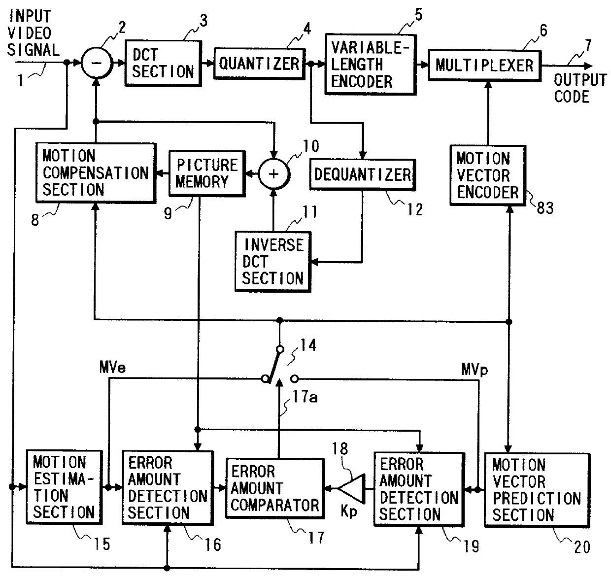
a motion compensation encoding apparatus according to the present invention will be described in the following. FIG. 1 is a general system block diagram showing the configuration of this embodiment. In FIG. 1, component which correspond to component in the prior art example of FIG. 11 are indicated by identical reference numerals. This embodiment differs from FIG. 11 in that it includes error amount detectors 16, 19, an error amount comparator 17, a factor multiplier 18, a motion vector switch 14 and a motion vector prediction section 20, while in addition, the operation of the picture memory 9 is somewhat different from that of the example of FIG. 11, and the embodiment preferably utilizes a motion vector encoder 83 which is a modification of the motion vector encoder 13 of FIG. 11 as described hereinafter. This embodiment also differs from the prior art example in that an operation of judging motion vectors is executed as described hereinafter, however the motion compensation enco...

second embodiment

the invention will be described, with FIG. 9 being a general system block diagram showing the configuration of this embodiment. In FIG. 9, component which correspond to component in FIG. 1 are indicated by identical reference numerals. The embodiment of FIG. 9 differs from that of FIG. 1 by including a quantization control section 31, code amount calculation sections 32, 34, and an adjustment control section 33. In addition, the operation of the factor multiplier 18 is somewhat different from that of the embodiment of FIG. 1.

The code amount measurement section 32 monitors the overall amounts of code which are being generated by the apparatus, and supplies corresponding information to the quantization control section 31. The quantization control section 31 establishes a suitable value for the quantization step size, in accordance with the detected amount of generated code, and supplies corresponding step size information to the quantizer 4 and to the adjustment control section 33, e....


PUM


Abstract

In a video motion compensation encoding apparatus in which each of periodically selected pictures is encoded as successive blocks of picture elements, by encoding of the prediction error amounts obtained for each block in conjunction with variable-length encoding by a motion vector encoder of motion vectors which are utilized in motion compensation processing to derive the prediction error amounts, each of these motion vectors is selected by a comparator-controlled switch either as an estimated motion vector derived by a conventional type of motion estimation section or as a predicted motion vector derived by a motion vector prediction section based on previously encoded motion vectors, with the estimated motion vector being selected only if it is found that an amount of prediction error which would occur from using the predicted motion vector is significantly greater than that which would result from using the estimated motion vector. A higher probability of encoding successively identical motion vectors is thereby achieved, resulting in greater encoding efficiency.

Description

1. Field of the InventionThe present invention relates to high-efficiency encoding of video information in the form of a stream of pictures expressed by a video signal, for the purpose of transmitting or storing the video information, whereby the pictures can be conveyed as a smaller amount of code than has been possible in the prior art.2. Description of the Related ArtTypical methods of high-efficiency encoding of video information which are widely used at present are the MPEG-1 or MPEG-2 standards, i.e. Moving Picture Experts Group international encoding standards which have been set by the IEC / ISO. With an MPEG encoding system, certain periodically selected pictures (transmitted as respective frames of a digital video signal, each picture being conveyed as an array of pixels each expressed by a digitized sample) are encoded by motion compensation, with each picture being encoded as a set of blocks of pixels. With motion compensation, a part of a preceding picture is shifted spat...

Claims


Application Information

Patent Timeline
IPC IPC(8): H04N7/26H03M7/36H04N5/92H04N19/105H04N19/154H04N19/196H04N19/46H04N19/463H04N19/50H04N19/51H04N19/517H04N19/625H04N19/70H04N19/91
CPCH04N19/56H04N19/517H04N19/51
Inventor SUGIYAMA, KENJI
Owner RAKUTEN INC
Features
  • Generate Ideas
  • Intellectual Property
  • Life Sciences
  • Materials
  • Tech Scout
  • Unparalleled Data Quality
  • Higher Quality Content
  • 60% Fewer Hallucinations
Learn More