Stake and rail assembly

Inactive Publication Date: 2000-11-28
NEWSOME REGINALD W
View PDF10 Cites 24 Cited by
  • Summary
  • Abstract
  • Description
  • Claims
  • Application Information

AI Technical Summary

Benefits of technology

It is therefor an object of the present invention to provide a stake and rail assembly for pickup trucks and other similar cargo carrying vehicles that is easy to install and provides firm and secure attachment of the rear wall extension over the tailgate such that movement thereof and the noise generated thereby is minimized.
It is another object of the present invention to provide such a stake and rail assembly that provides a convenient, secure and "on-board" storage location for the rear wall extension over the tailgate when the same is not in use.
It is yet a further object to provide such a stake and rail assembly that is "universal", i.e. easily adjustable to fit a variety of vehicles with only minor or no modification.
According to the present invention, there is provided a stake and rail assembly for increasing the vertical cargo carrying capacity of pickup trucks and the like comprising a fro

Problems solved by technology

In general, the volume cargo carrying capacity of the truck bed is limited by the height of the extending side walls and end walls.
Two common problems exist with most such homemade stake and rail assemblies.
First, although the end wall extension that rides above the front end of the bed may be attached by bolts, fittings or otherwise to the side wall extensions, the end wall extension that rides over the tailgate portion of the bed is either not attached, only loosely attached, or held by a slide bolt or some similar arrangement to the side wall extensions.
Thus when the

Method used


Image

  • Stake and rail assembly
  • Stake and rail assembly
  • Stake and rail assembly

Examples


Example

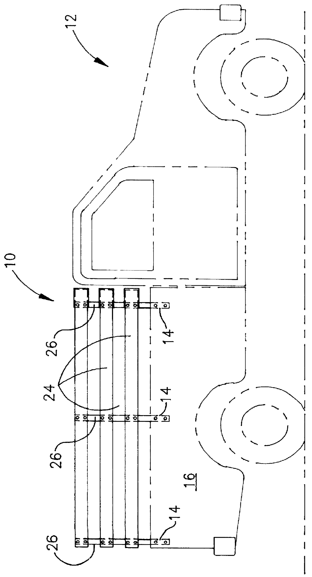
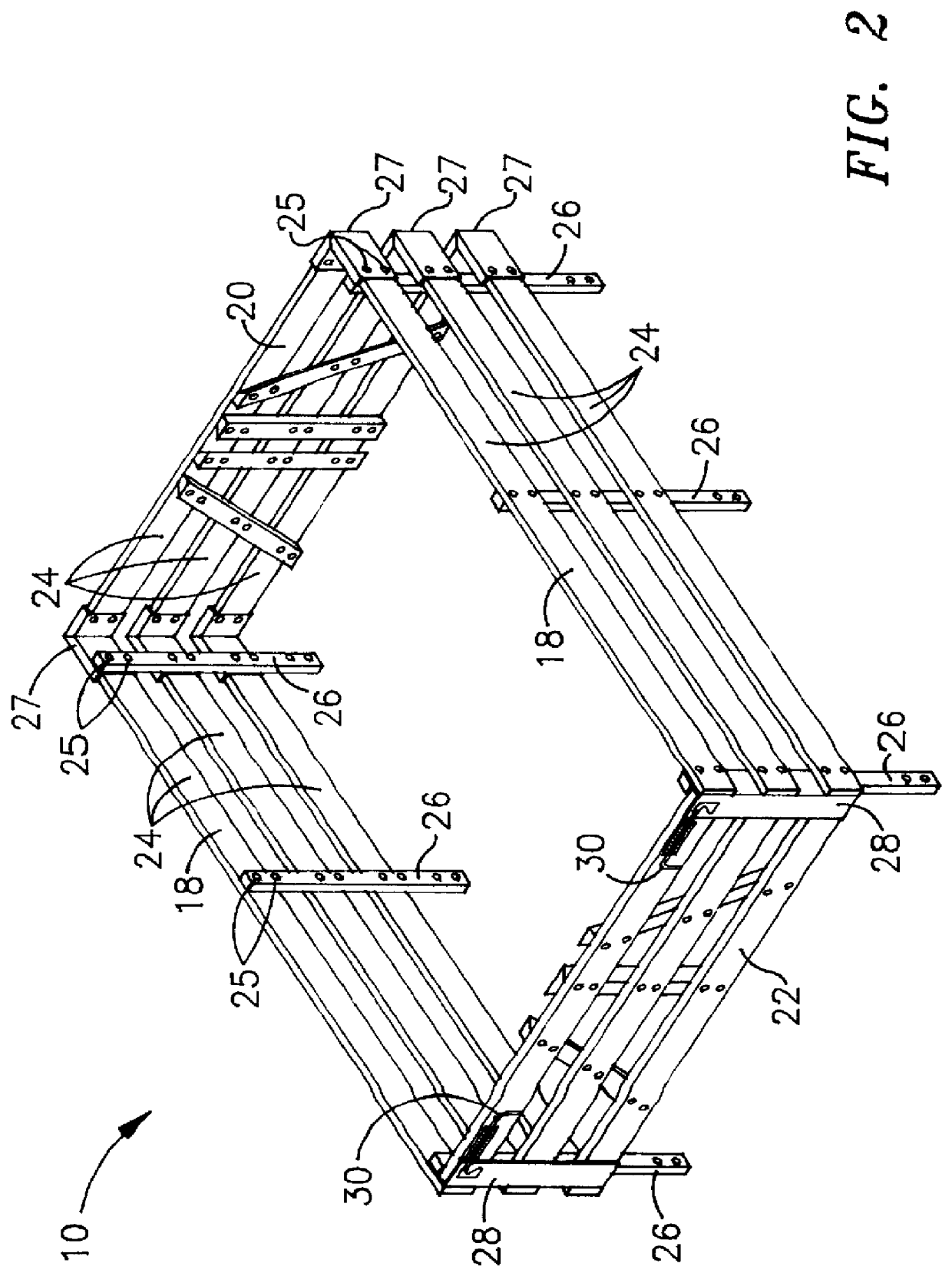
As shown in FIG. 1, the stake and rail assembly 10 of the present invention is conventionally mounted on a pickup truck 12 having a series of cavities 14 at the corners and along the sides, i.e. in the side walls 16 of its bed. Stake and rail assembly 10 is shown most clearly in FIG. 2 which depicts assembly 10 in its fully assembled condition off of pickup truck 12, but in the same orientation as shown in FIG. 1. As will be noted hereinafter, the presence of cavities to receive the stakes is not essential, as the stakes can be bolted to the side walls of the pickup truck or other vehicle using holes 13 located at the base of all of stakes 26, if appropriate. For purposes of general discussion herein, however, reference will generally be made to insertion into preexisting cavities, it being understood that bolting is an obvious and included optional installation method.

As depicted in FIG. 2, stake and rail assembly 10 comprises a pair of side walls 18, a front end wall 20 and a rear...


PUM


Abstract

A stake and rail assembly for increasing the cargo carrying capacity of a pickup truck or the like vehicle comprising: a front wall, a pair of generally parallel side walls, a rear wall and upright stakes for insertion into the cavities in the vehicle or attachment by bolts to the vehicle, wherein the front and side walls comprise a plurality of horizontal rails attached to the stakes to form three sides of an enclosed volume, the rear wall comprises a plurality of horizontal rails, a first pair of angularly mounted members and at least one upright attached to the horizontal rails of the rear wall and capable of engaging a parallel second pair of angularly mounted members and at least one upright on the front wall when the rear wall is vertically juxtaposed with the front wall. According to various preferred embodiments of the invention, 1) the surfaces of the angularly mounted members and the uprights are cut to provide engagement when the front and rear walls are vertically juxtaposed, 2) the ends of all front wall and sidewall rails include slots that engage bolts inserted through holes in two part brackets that serve to join the front wall and side wall rails, and 3) the rear wall includes spring biased locking mechanisms that engage apertures in a second set of brackets attached to the rear extremities of the side walls.

Description

FIELD OF THE INVENTIONThe present invention relates to equipment for increasing the cargo carrying capability of vehicles and more specifically to a stake and rail assembly for increasing the load carrying capability of pick-up trucks and the like.BACKGROUND OF THE INVENTIONAs is well known, pickup trucks are commonly used for hauling light cargo such as crates and boxes. Pickup truck beds are formed of floor and extending side walls and end walls, one of the latter being hinged to form a tailgate. In general, the volume cargo carrying capacity of the truck bed is limited by the height of the extending side walls and end walls.One means for increasing the cargo capacity of pickup trucks including those having cavities formed in the side walls or corners thereof is to use a stake and rail assembly to increase the height of the extending side and end walls of the truck bed. The stake members of the of the assembly are dimensioned to fit within the cavities of the side walls or corners...

Claims


Application Information

Patent Timeline
IPC IPC(8): B62D33/02B62D33/023
CPCB62D33/023
Inventor NEWSOME, REGINALD W.
Owner NEWSOME REGINALD W
Why Eureka
Try Eureka