Induction hardening apparatus for a crankshaft

a crankshaft and induction hardening technology, which is applied in the direction of electrical equipment, induction heating, electric/magnetic/electromagnetic heating, etc., can solve the problems of increasing the wear on the coil assembly, affecting the service life of the induction hardening equipment, and affecting the service life of the crankshaft, etc., to achieve the effect of improving the induction hardening apparatus

Inactive Publication Date: 2000-11-28
CONTOUR HARDENING
View PDF28 Cites 15 Cited by
  • Summary
  • Abstract
  • Description
  • Claims
  • Application Information

AI Technical Summary

Benefits of technology

One object of the present invention is to provide an improved induction hardening apparatus for a workpiece.

Problems solved by technology

This metal-to-metal contact accelerates the wear on the coil assembly, necessitating that the coil assembly be replaced periodically.
The need to replace the induction coil assembly represents not only an added cost factor but also down time to the induction hardening equipment.
However, direct contact between the coil assembly and the portion of the crankshaft to be induction hardened is seen as a substantial disadvantage, not only due to wear of the induction coil assembly and the horizontal mounting of the crankshaft, but for the additional reasons which are set forth below.
When the induction coil assembly contacts the pins and / or bearing surfaces, it is difficult to identify the wear condition of the coil assembly.
By riding directly on the crankshaft surfaces, the contacting surface of the induction coil assembly is effectively hidden from view, thereby making it difficult to assess the level or degree of wear on the coil assembly.
This in turn means that the induction coil assembly can be run too long and reach a point at which it arcs out and this typically ruins the part and ruins or damages the coil assembly.
Contact between the coil assembly and the crankshaft often results in marring or galling of the crankshaft surface and this requires extra grind stock which can then be machined away in order to grind out the surface imperfections.
While there are other designs which suggest a vertical orientation for the workpiece, these other designs are limited to camshafts, not crankshafts.
This results in a pin orbit of substantial size and travel relative to whatever cam orbit might be present.
In turn, this results in substantially different challenges and problems for the design of a suitable induction coil tracking apparatus, with the crankshaft presenting the more challenging design task.

Method used


Image

  • Induction hardening apparatus for a crankshaft
  • Induction hardening apparatus for a crankshaft
  • Induction hardening apparatus for a crankshaft

Examples


Embodiment Construction

For the purposes of promoting an understanding of the principles of the invention, reference will now be made to the embodiment illustrated in the drawings and specific language will be used to describe the same. It will nevertheless be understood that no limitation of the scope of the invention is thereby intended, such alterations and further modifications in the illustrated device, and such further applications of the principles of the invention as illustrated therein being contemplated as would normally occur to one skilled in the art to which the invention relates.

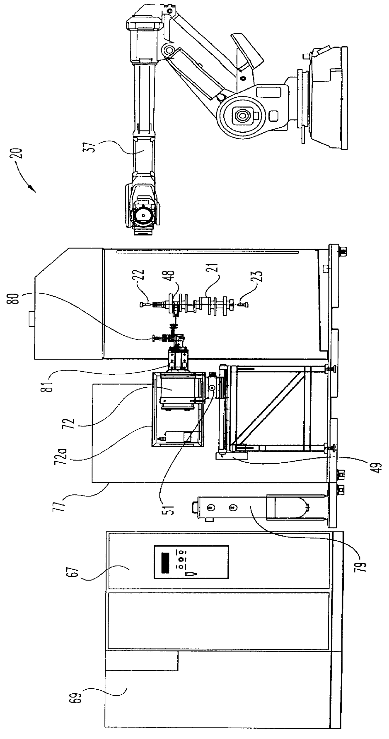
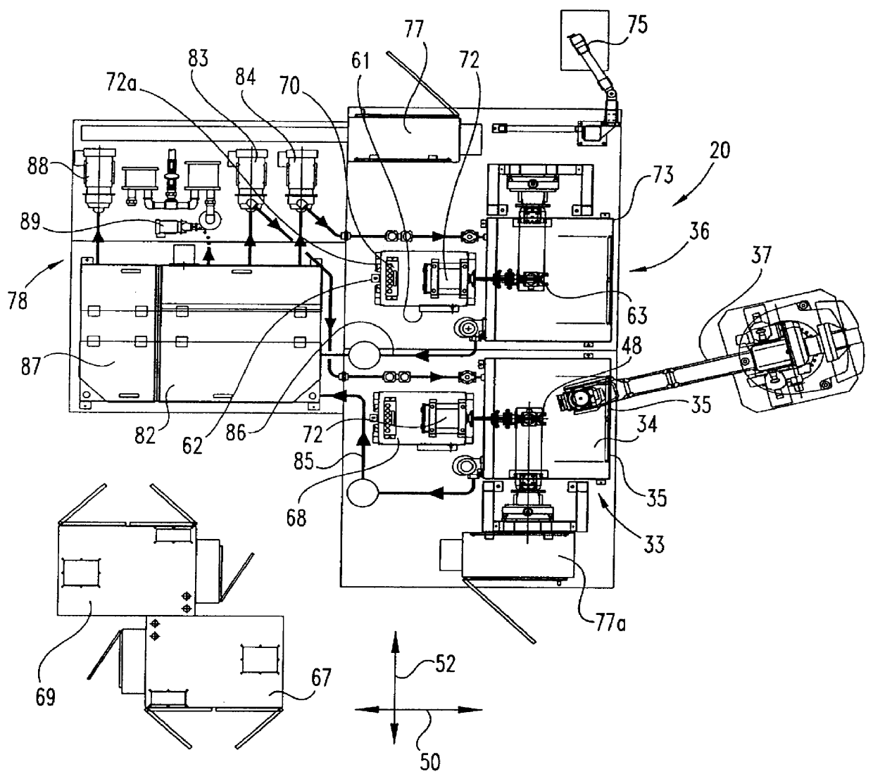
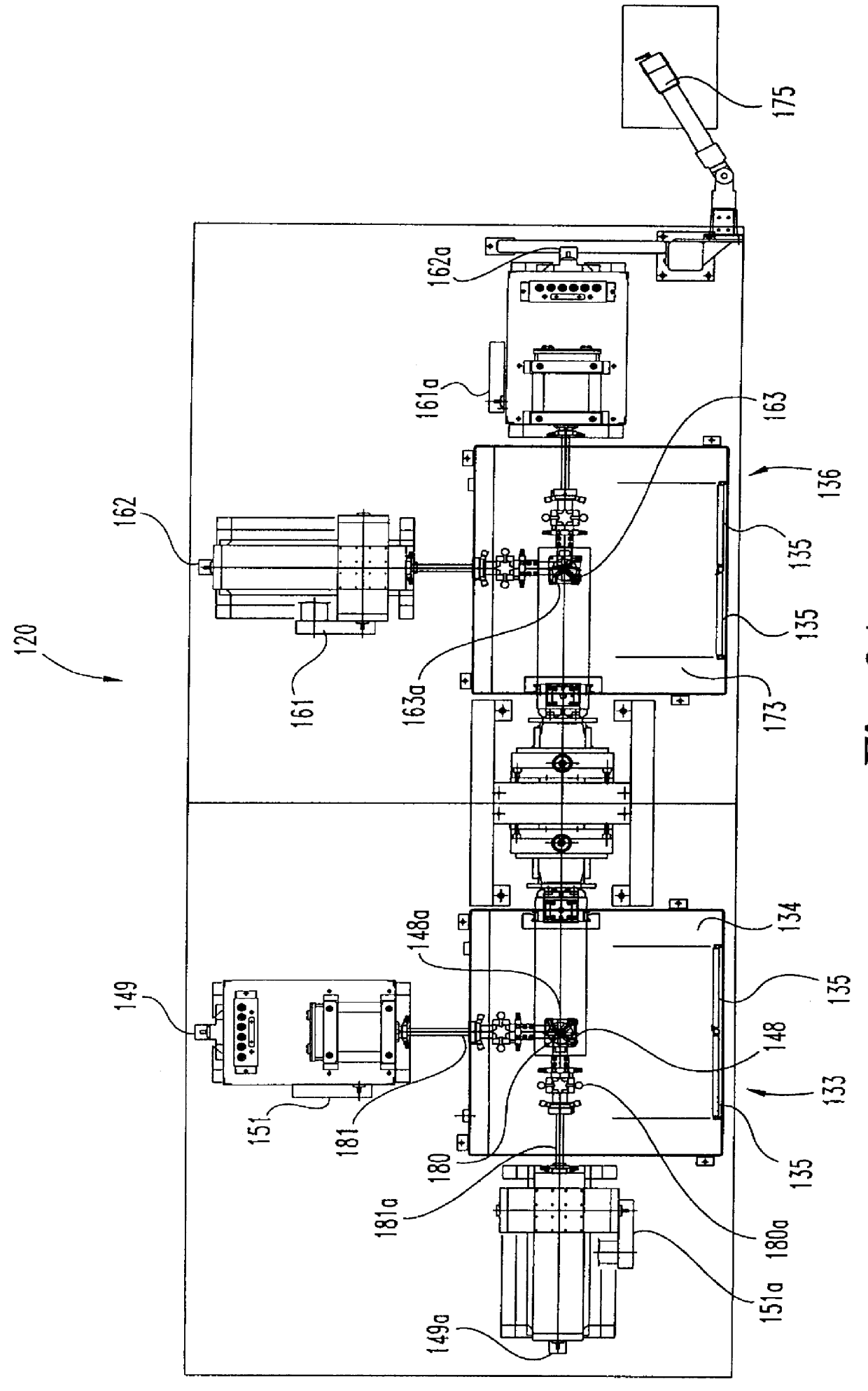
Referring to FIGS. 1, 2, 3, 4, 5, 6, and 6A, there is illustrated an induction hardening apparatus 20 which is constructed and arranged for inductively heating and quench hardening a crankshaft 21. Crankshaft 21 is positioned in a vertical orientation and supported between centers 22 and 23. The illustration of the upper center 22 should be regarded as merely diagrammatic for the purpose of representing a true vertica...


PUM

PropertyMeasurementUnit
right angle relationshipaaaaaaaaaa
angleaaaaaaaaaa
electrical currentaaaaaaaaaa

Abstract

An induction hardening apparatus for inductively heating and quench hardening a crankshaft includes an arrangement of two workstations similarly configured and a robotic device indexing the crankshaft from a first workstation to a second workstation. The induction hardening apparatus is designed with a single induction coil located at the first workstation for the sequential induction heating and quench hardening of the pins of the crankshaft. At the second workstation, a single induction coil is used for the bearing surfaces of the crankshaft. One feature of the present invention is that the induction coils do not contact the surfaces of the crankshaft which are being inductively heated and quench hardened. Crankshaft dimensions and geometry are prograrmned into servodrive systems which move the corresponding coil in X and Y directions accurately tracing the orbit or path of each pin and each bearing surface. Another feature of the present invention is the use of an offset 180 degree coil which provides improved heating patterns in less time than traditional 90 degree coils.

Description

BACKGROUND OF THE INVENTIONThe present invention relates in general to methods and apparata for inductively heating and quench hardening a crankshaft. More specifically, the present invention relates to inductively heating and quench hardening a crankshaft, which may be oriented either horizontally or vertically, wherein the induction coil assembly (or assemblies) do not contact the surfaces of the crankshaft which are to be induction hardened. Computer controlled servomotors and X and Y drive systems are used to position and move the induction coil assembly relative to a crankpin portion of the crankshaft as the crankshaft rotates at a predetermined RPM. The travel of the induction coil assembly is based upon mathematical formulae and the crankshaft geometry, including crankshaft dimensions and the particular location of the crankpin portion to be induction hardened relative to the longitudinal axis of the crankshaft.An automotive crankshaft is made up of a series of crankpins, one...

Claims


Application Information

Patent Timeline
Patent Type & Authority Patents(United States)
IPC IPC(8): H05B6/40H05B6/36
CPCH05B6/36H05B6/102
Inventor STORM, JOHN M.STEWART, MAX E.GIBBS, SPENCER L.
Owner CONTOUR HARDENING
Why Eureka
Try Eureka