Free running RF identification system with increasing average inter transmission intervals

a free-running, inter-transmission interval technology, applied in the field of data communication systems, can solve the problems of large communication channel bandwidth, inconvenient for many narrow band applications, data loss in response signals, etc., and achieve the effect of increasing the count of the second counter

Inactive Publication Date: 2000-11-28
ACTIVE NETWORK LLC
View PDF17 Cites 41 Cited by
  • Summary
  • Abstract
  • Description
  • Claims
  • Application Information

AI Technical Summary

Benefits of technology

The control means for the interval generating means may include: a second counter for controlling the number of bits of the random number and in the first counter to be compared; and a third counter, an input of the third counter being connected to the output of the comparator, to be incremented with each transmission; an output of the third counter being connected to an input of the second counter, to increment the second counter after a predetermined number of transmissions, thereby to increase the count of the second counter and hence the number of bits to be compared.

Problems solved by technology

However, when a plurality of transponders are energized simultaneously, it may well happen that the response signals overlap in time, that the transmissions clash and that the data in the response signals is lost.
The major disadvantage of this protocol is that it requires a larger communications channel bandwidth.
Accordingly, it is not suitable for many narrow band applications.
However, if a large number of transponders are present, the probability of a successful transmission is reduced and the time required to receive the transmissions from all the transmitters becomes larger, i.e. the communication channel becomes congested.
If the number of transponders is increased too much, the probability of a successful transmission may become so low, that the time required to receive a transmission from each of the transponders becomes unpractically long (even infinitely long).
With these systems and if the maximum inter-transmission interval is made shorter, the communications channel may saturate with a relatively small number of transponders, but on the other hand the time required successfully to read a small number of transponders would be short.
Furthermore, if the maximum inter-transmission interval is made longer to accommodate a larger transponder population, the total time to read the transponders (even a small number of transponders), may be too long for many applications.
In practice this means that a specific transponder can only be used in an application where its maximum inter-transmission interval is compatible with the number of transponders that would be present and the time required successfully to read the transponders.

Method used


Image

  • Free running RF identification system with increasing average inter transmission intervals
  • Free running RF identification system with increasing average inter transmission intervals
  • Free running RF identification system with increasing average inter transmission intervals

Examples


Embodiment Construction

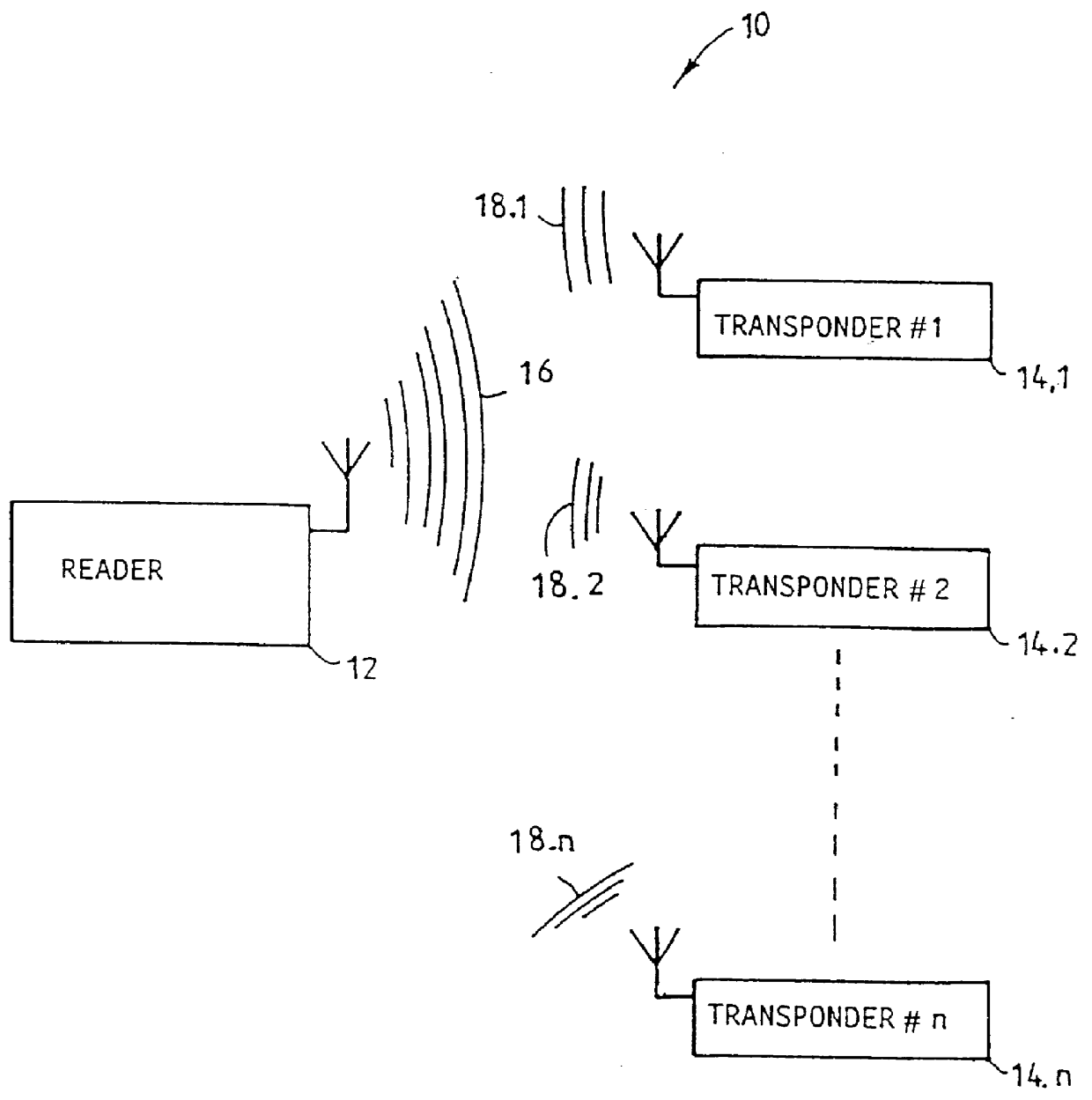
In FIG. 1, a radio frequency (RF) electronic identification system 10 is shown. The system includes an interrogator or reader 12 and a plurality of transmitters, in the form of passive transponders 14.1 to 14.n.

In use, the reader 12 transmits an energizing signal 16 towards the transponders 14.1 to 14.n. Each of the transponders is energized in known manner and automatically responds with response signals 18.1 to 18.n, for example by backscatter modulating the energizing signal 16. The response signals 18.1 to 18.n normally include data relating to a unique Identification (ID) code associated with the relevant transponder.

The response signals 18.1 to 18.n are received by a receiver (not shown) of the reader and the data is read by the reader, to identify the transponders and hence articles (not shown) that may be associated with the transponders and / or to count the number of transponders and hence articles.

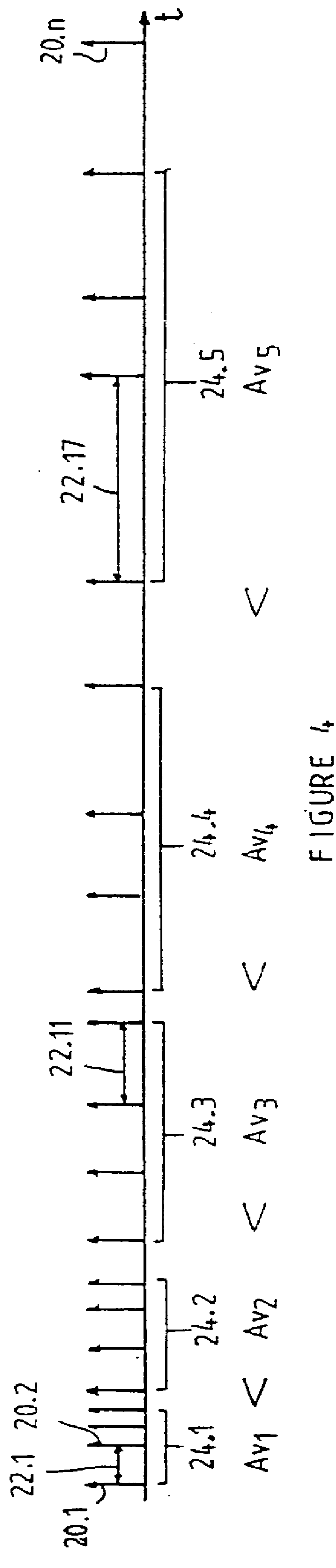
As shown in FIG. 3, each signal 18.1 to 18.n includes a plurality of repeated...


PUM


Abstract

An RF electronic identification system 10 is disclosed and claimed. The system includes a reader 12 and a plurality of transponders 14.1 to 14.n. When energized by an interrogation signal from the reader, each transponder automatically responds by repeatedly retransmitting a signal burst including identification code data associated with the relevant transponder. Each transponder includes circuitry 34 for generating random inter-transmission intervals for separating any two consecutive signal bursts and a controller 42 for the generation circuitry, to cause an average value of the inter-transmission intervals over a period of time to vary, preferably to increase. This feature enhances the probability and speed of reading a transponder population of almost any size.

Description

INTRODUCTION AND BACKGROUNDTHIS invention relates to data communication systems, more particularly to interrogation systems such as electronic identification systems.Radio frequency (RF) electronic identification systems including an interrogator or reader and a plurality of passive transponders are well known in the art. In use, the reader energizes the transponders by transmitting an interrogation signal. Each energized transponder automatically responds with a response signal, normally including an identification code characteristic of the transponder. The response signals are received by the reader and the data is read. The data may be utilized to identify transponders and goods associated with the transponders and / or to count the transponders and / or goods. However, when a plurality of transponders are energized simultaneously, it may well happen that the response signals overlap in time, that the transmissions clash and that the data in the response signals is lost.Accordingly,...

Claims


Application Information

Patent Timeline
Patent Type & Authority Patents(United States)
IPC IPC(8): G08B13/14G06K19/07G06K7/00
CPCG06K7/0008G06K7/10059G08B21/0227G08B13/1427G06K19/0723
Inventor VAN EEDEN, HENDRIK LODEWYK
Owner ACTIVE NETWORK LLC
Why Eureka
Try Eureka