Power cutter

a power cutter and cutting blade technology, applied in the field of power cutters, can solve the problems of inevitably leaking out through the gap between the cutting blade and the extended portions of the barrier, the dust generated in the cutting of concrete members or the like, and the subject of conventional power cutters

Inactive Publication Date: 2000-12-05
KIORITZ
View PDF13 Cites 46 Cited by
  • Summary
  • Abstract
  • Description
  • Claims
  • Application Information

AI Technical Summary

Benefits of technology

Accordingly, it is possible according to the power cutter of the invention to minimize the quantity of dust that might be discharged, without being sucked by the fan, through the gap between the cutting blade and the barrier wall.

Problems solved by technology

However, this conventional power cutter is subject to the following problem.
However, if such a slit-shaped opening is formed in the barrier, a gap is inevitably formed between the cutting blade and the extended portions of the barrier.
Therefore, the dust generated in cutting concrete members or the like inevitably leaks out through the gap toward the rear side of the cutting blade.

Method used


Image

  • Power cutter
  • Power cutter
  • Power cutter

Examples


Embodiment Construction

The invention will be further explained with reference to the drawings depicting an illustrative embodiment of the invention.

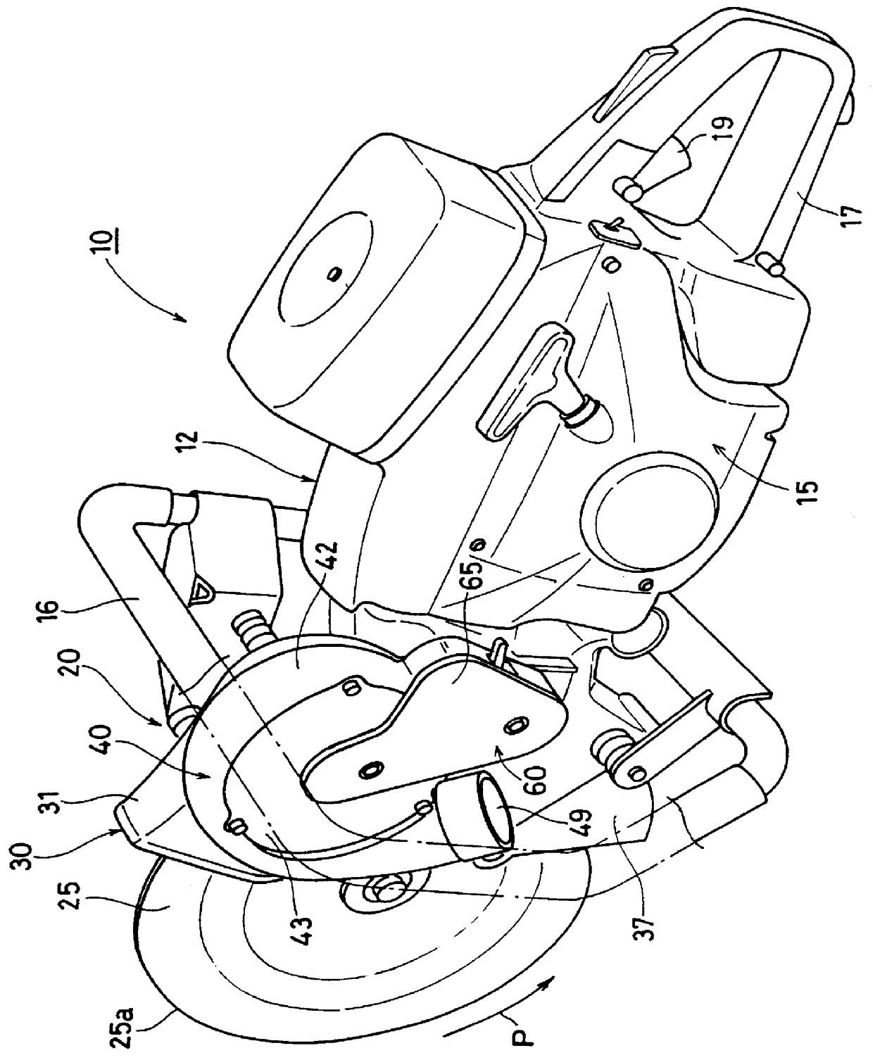
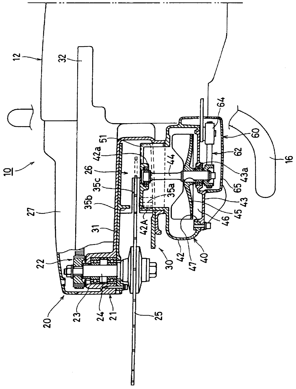
FIG. 1 shows a general perspective view illustrating one embodiment of an engine cutter 10 exemplifying a portable power cutter according to the invention. FIG. 2 is a partially sectioned plan view illustrating a main portion of the engine cutter 10 shown in FIG. 1.

The engine cutter 10 shown in FIG. 1 comprises a main body 12 which is provided at the central portion thereof with a small air-cooled two-stroke gasoline engine 15 (hereinafter referred to simply as an engine) functioning as a motor. To this main body 12 is attached a rear handle 17 extending in the longitudinal direction of the engine cutter 10 and being provided at the rear portion thereof with a throttle trigger 19, etc. A front handle 16 is attached to the main body 12 so as to extend upward from the central bottom portion of the main body 12 to cross over the upper forward portion of the main ...


PUM

PropertyMeasurementUnit
widthaaaaaaaaaa
cross-sectional areaaaaaaaaaaa
shapeaaaaaaaaaa

Abstract

A power cutter which comprises a main body provided with a motor, a work-cutting portion including a circular cutting blade to be rotated by the motor and a safety cover covering both sides of an edge portion of the cutting blade so as to form a dust-discharging passageway, a fan attached to the safety cover for sucking and removing dust generated during cutting operations through the dust-discharging passage, a barrier wall attached to the safety cover so as to intercept the dust-discharging passageway, and a main dust-sucking port and a supplementary dust-sucking port disposed respectively in front of and behind the barrier wall as viewed in the rotational direction of the cutting blade.

Description

1. Field of the InventionThis invention relates generally to a power cutter having a circular cutting blade which is adapted to be rotated by means of a motor, such as a small air-cooled two-stroke gasoline engine or an electric motor. In particular, the invention relates to a portable power cutter which is provided with a fan for sucking and removing dust generated in cutting concrete members, or the like, with the circular cutting blade.2. The Prior ArtAs described in Japanese Patent Publication H / 7-14570, a portable power cutter provided with a fan for sucking and removing dust has been proposed or put into practical use. Namely, this conventional portable power cutter includes a main body provided with a motor, a circular cutting blade which is adapted to be rotated by the motor, a safety cover disposed on and covering both sides of an edge portion of the cutting blade so as to form a dust-discharging passageway, and a fan which is attached to the safety cover for sucking dust g...

Claims


Application Information

Patent Timeline
Patent Type & Authority Patents(United States)
IPC IPC(8): B23D59/00B23Q11/00B23Q11/06B08B15/00B08B15/04E01C23/09B28D7/02F02B63/00
CPCB08B15/04B23Q11/06B23Q11/0046B23D59/006
Inventor YAMAMI, HIROFUMIIIDA, GIICHI
Owner KIORITZ
Why Eureka
Try Eureka