Method of spray forming metal deposits using a metallic spray forming pattern

a spray forming pattern and metal deposit technology, applied in the direction of foundry patterns, manufacturing tools, moulding apparatus, etc., can solve the problems of relatively time-consuming and expensive methods, and the removal of metal deposits from ceramic spraying patterns is a relatively tedious and time-consuming procedur

Inactive Publication Date: 2000-12-05
FORD GLOBAL TECH LLC
View PDF20 Cites 34 Cited by
  • Summary
  • Abstract
  • Description
  • Claims
  • Application Information

AI Technical Summary

Problems solved by technology

While the above method produces acceptable deposits, the method is relatively time consuming and expensive.
Also, the removal of the deposit from the ceramic spraying pattern is a relatively tedious and time consuming procedure.

Method used


Image

  • Method of spray forming metal deposits using a metallic spray forming pattern
  • Method of spray forming metal deposits using a metallic spray forming pattern
  • Method of spray forming metal deposits using a metallic spray forming pattern

Examples


Embodiment Construction

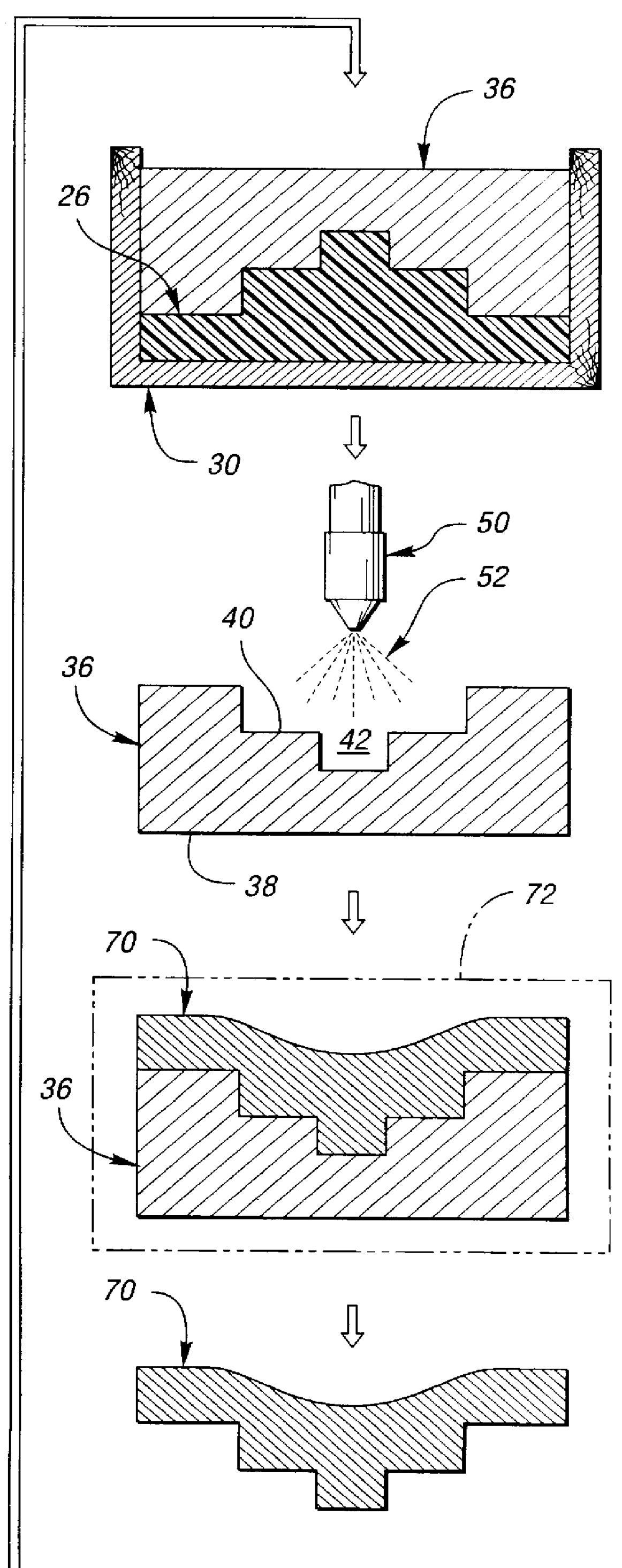
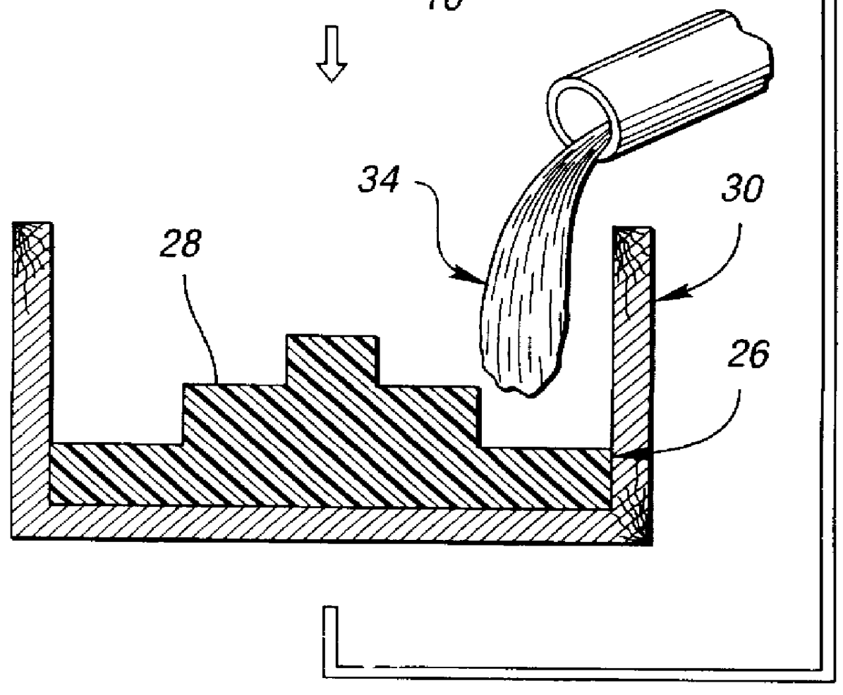
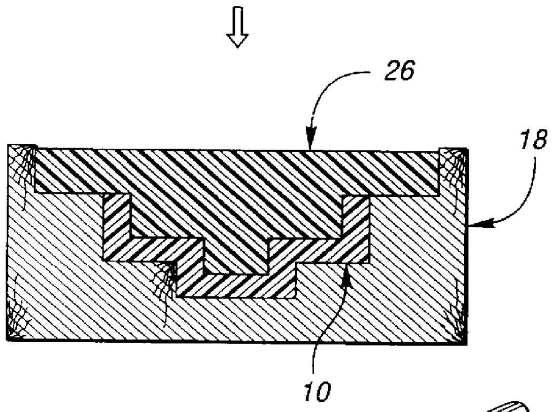
The method of the present invention comprises at least four basic steps: (a) providing a master pattern; (b) forming a spray forming pattern of a first metal having a melting point at a first temperature, the spray forming pattern having a surface which defines a cavity within the spray forming pattern, the cavity having the general shape of the master pattern; (c) spraying metal particles, different than the first metal, onto the spray forming pattern to form a deposit on the spray forming pattern; and (d) heating the deposit and the spray forming pattern to a second temperature, higher than the first temperature, to melt the spray forming pattern from the deposit, the resulting deposit having the general shape of the master pattern.

The master pattern 10, shown schematically in FIG. 1, is preferably polymeric and may be created using solid-free form fabrication techniques controlled by a CAD / CAM model. Free-formed fabrication can comprise stereolithography, cubital, laminated or fo...


PUM

PropertyMeasurementUnit
thicknessaaaaaaaaaa
surface temperatureaaaaaaaaaa
temperatureaaaaaaaaaa

Abstract

A spray forming pattern of a first metal having a melting point at a first temperature is formed. The spray forming pattern has a surface defining a cavity that has the shape of a master pattern. Steel particles having a carbon content in the range of 0.01-0.9% by weight are sprayed onto the spray forming pattern to form a deposit on the spray forming pattern. The deposit has a thickness of at least 0.5 inches and the temperature of the steel particles increases as the thickness of the steel deposit increases. The spraying conditions are controlled so that the steel particles coming into contact with the spray forming pattern results in a surface temperature of the spray forming pattern of less than about 80 DEG C. The deposit and the spray forming pattern are heated to a second temperature, which is higher than the first temperature, to melt the spray forming pattern from the deposit. The resulting deposit has the general shape of the master pattern.

Description

The present invention relates to the making of prototype tools, and more particularly to a method of spray forming of metal deposits.Spray forming has become an accepted technique for producing steel prototype tooling (such as dies or molds) in a fraction of the time needed to make steel tooling conventionally. Spray forming techniques up to date have typically involved the following steps: (i) casting and solidifying a ceramic spraying pattern about a plastic master pattern of the tool to be produced; (ii) spraying metallic particles onto the ceramic pattern; (iii) allowing the sprayed metallic particles to cool thereby forming a metal deposit having the general shape of the master pattern; and (iv) separating the metal deposit from the ceramic mold pattern.While the above method produces acceptable deposits, the method is relatively time consuming and expensive. For instance, it can take up to four days to form the ceramic spraying pattern. Also, the removal of the deposit from th...

Claims


Application Information

Patent Timeline
Patent Type & Authority Patents(United States)
IPC IPC(8): B22C9/00B22C7/00B22D23/00C23C4/18
CPCB22C7/00B22C9/00C23C24/04C23C4/185C23C4/08B22D23/003B33Y80/00
Inventor KINANE, JEFFREY ALANGRINBERG, GRIGORIYCOLLINS, DAVID ROBERTPERGANDE, PAUL EARL
Owner FORD GLOBAL TECH LLC
Why Eureka
Try Eureka