Electronic control unit with electrical connector

a technology of electronic control unit and electrical connector, which is applied in the direction of fixed connection, coupling device connection, braking system, etc., can solve the problems of material fatigue at the solder joint, degradation of the reliability of the printed circuit board, and possible breakag

Inactive Publication Date: 2000-12-05
ADVICS CO LTD
View PDF5 Cites 70 Cited by
  • Summary
  • Abstract
  • Description
  • Claims
  • Application Information

AI Technical Summary

Problems solved by technology

Where the socket connector is fixed in position with the connector terminals electrically connected directly with the printed circuit board through electrical joints formed by, for example, soldering, repeated application of the alternating compressive and tensile loads to the printed circuit board will eventually result in degradation of the reliability of the printed circuit board.
However, the difference between the coefficient of thermal expansion of a material for the connector terminals in the socket connector and that of a material for the printed circuit board is apt to allow thermal stresses to develop at the solder joints which eventually leads to material fatigue at the solder joints.
Once this occurs, breakage is likely to result in at one or some of the solder joints.
To complete the control unit housing 100, however, the structure shown in FIG. 5 requires the use of the separate casings 103 and 201 which tends to increase the cost of manufacture.
Accordingly, not only does the cost of manufacture increase additionally, but also the use of the waterproof seal may constitute a cause of reduction in reliability.
In addition, alignment of the tip of that end portion of each connector terminal 202 with a corresponding perforation in the partition wall is indeed difficult to achieve and even the slight misalignment would require readjustment in position of the connector terminals 202 relative to the respective perforations in the partition wall.
This complexity indeed increases the cost of manufacture.
Although the connector terminals 202 may be insert-molded together with the control unit housing 100 during the molding of the latter, a complicated and expensive mold would be required in such case, adding cost to the final product.
In addition, since the structure shown in FIG. 6 requires the connector terminals 202 to be press-fitted into the corresponding apertures in the partition wall from the interior of the circuit casing 103, it is impossible to reduce the size of a portion where the connector terminals 202 are fixed even though they can be formed to have the same shape as the corresponding socket terminals in the plug-in connector, and a problem associated with reduction in physical strength of the partition wall would also occur if the connector terminals 202 are spaced a small pitch between the neighboring members of them.
However, the bending of the coil terminals for this purpose is required either before or after the coil terminals have been pierced under interference fit through the coil mounting seats.
In either case, it has been found that some of the coil terminals are apt to deviate from the design dimension when they are bent and, therefore, alignment of the coil terminals with corresponding perforations in the coil printed circuit board appears to be difficult to achieve without complicated and time-consuming procedures.
However, the resultant solder joints have been found sensitive to external stresses such as, for example, thermal stresses generated in the circuit board or the like which would be brought about by change in ambient temperature.

Method used


Image

  • Electronic control unit with electrical connector
  • Electronic control unit with electrical connector
  • Electronic control unit with electrical connector

Examples


Embodiment Construction

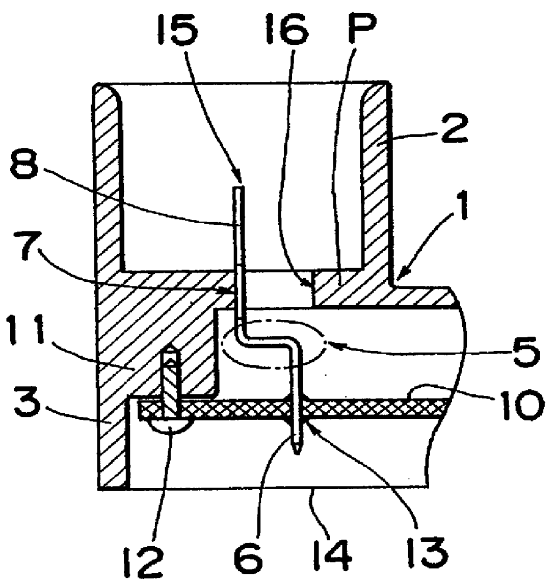
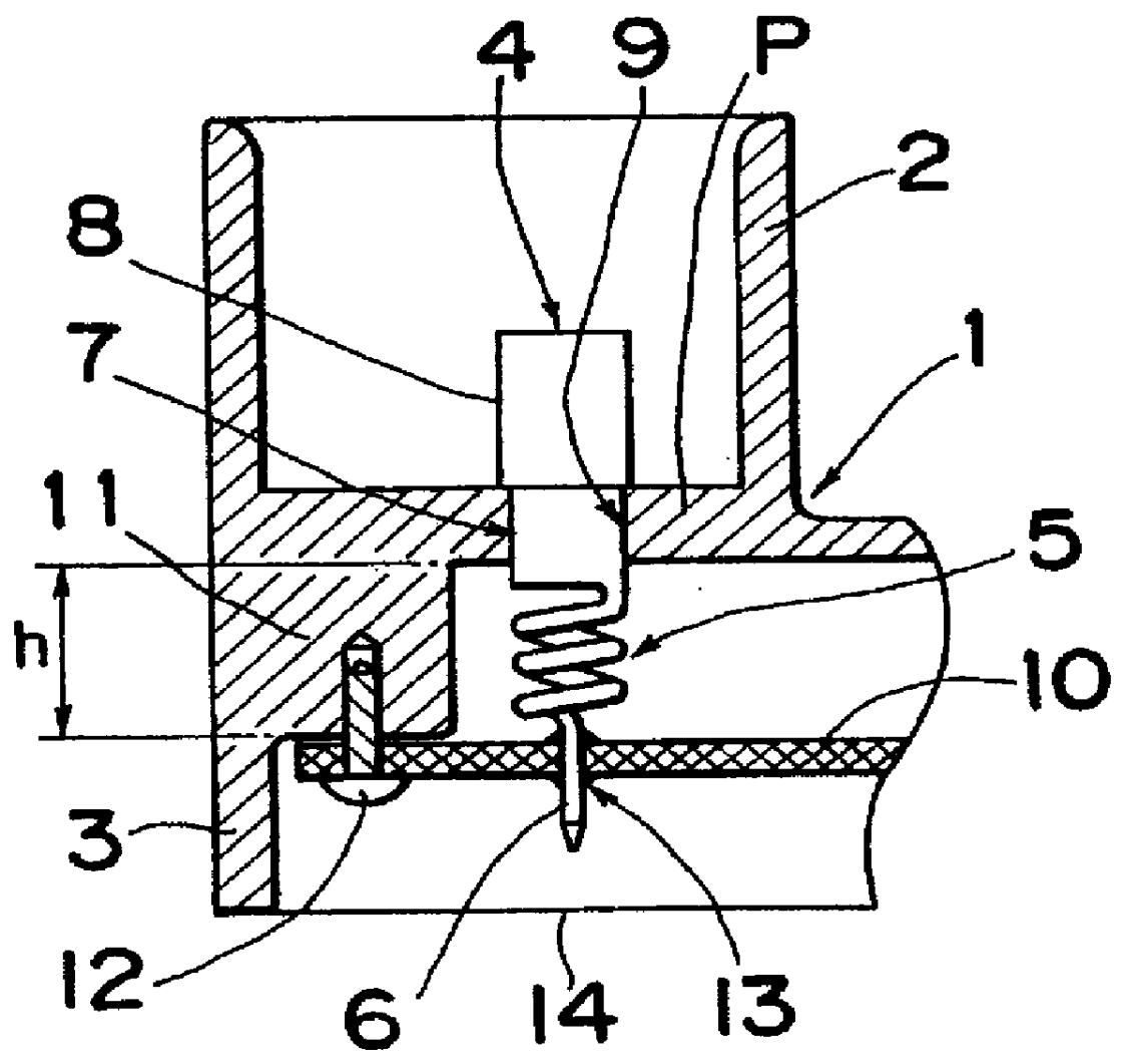
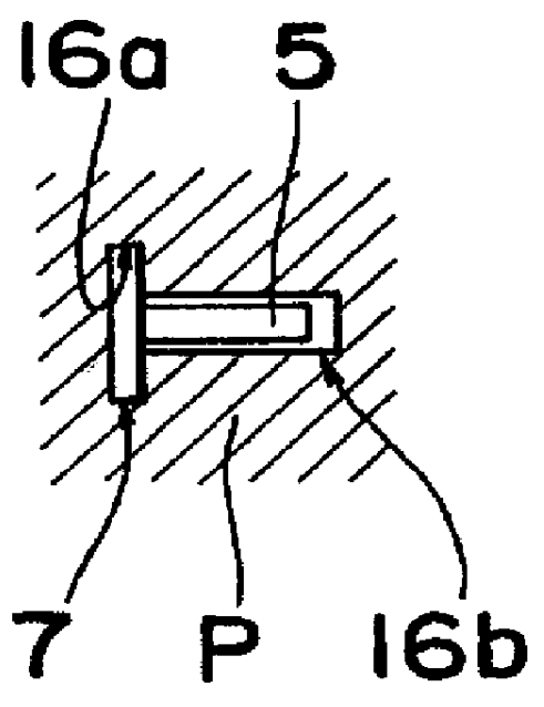
Referring first to FIG. 1, an electronic control unit comprises a unit housing 1 of one-piece construction including a connector casing 2 and a circuit casing 3 both formed integrally therewith and a partition wall P intervening between the connector and circuit casings 2 and 3. A printed circuit board 10 is supported inside the circuit casing 3 and fixed in position by means of one or more set screws 12 such as, for example, drive screws that are threaded into a frame portion integral with the circuit casing 3. At least one connector terminal 4 having a connecting end 6, a fixing portion 7 and an engaging portion 8 defined therein at different locations over the length thereof is press-fitted through a corresponding insertion hole 9, defined in the partition wall P, with the connecting end 6 pierced through a corresponding through-hole in the printed circuit board 10. The connected end 6 so inserted through the through-hole is soldered to a circuit element on the printed circuit bo...


PUM


Abstract

An electronic control unit has a connector intervening between an external load and a printed circuit board inside the unit housing including a circuit casing and a connector casing both formed integrally therewith. At least one connector terminal of the connector is provided with a buffering portion effective to absorb an external stress. This connector terminal can be accurately and precisely constrained in a housing and can provide a stabilized electrical connection with a high workability.

Description

1. Field of the InventionThe present invention generally relates to an electronic control unit of a kind required to have a waterproof structure suitable for use in an automobile and, more particularly, to the electronic control unit equipped with at least one electrical input / output connector having a plurality of terminal members adapted to be connected directly with a printed circuit board.2. Description of the Prior ArtThe electrical plug-in connector assembly providing for the input and output of one or both of an electrical power and electrical signals to the separate device has long been well known, which is generally made up of a plug-in connector and a socket connector for receiving the plug-in connector. While the plug-in connector assembly is available in various types, the present invention makes use of the type comprising the plug-in connector having a plurality of terminal sheaths and the socket connector having a corresponding number of connector terminals which are c...

Claims


Application Information

Patent Timeline
Patent Type & Authority Patents(United States)
IPC IPC(8): H01R43/02H05K7/12
CPCH01R9/091B60T8/3675H01R43/0256H01R12/58
Inventor SANADA, SATOSHI
Owner ADVICS CO LTD
Why Eureka
Try Eureka