Air cleaner having vanes with a winglike cross-section between a shroud and baseplate for rotation within a housing

a technology of air cleaner and shroud, which is applied in the direction of liquid fuel engine components, combination devices, dispersed particle filtration, etc., can solve the problems of deteriorating fan efficiency, noise and pressure loss, and deterioration of fan efficiency, so as to reduce the friction between the vane and the air flow. , the effect of enabling the efficiency of the fan and reducing energy loss

Inactive Publication Date: 2000-12-05
HITACHI LTD +1
View PDF7 Cites 39 Cited by
  • Summary
  • Abstract
  • Description
  • Claims
  • Application Information

AI Technical Summary

Benefits of technology

As explained above, since not more than four vanes are provided in a vane-wheel, friction between the vane and air flow is reduced, which enables efficiency of the fan and reduces energy loss.
In addition, since a reinforcement portion is disposed on a circular circumference of the base plate and the shroud, vibration of the base plate and the shr

Problems solved by technology

A problem in the related art is deterioration of the fan efficiency and increase of noise.
When the fan rotates, the edge induces turbulence of air, which results in increase of noise and pressure loss, and thereby an efficiency of the fan is deteriorated.
Another problem in the related art is increase of pressure loss along the surface of the vanes.
This increases friction between the air and the surfaces of the vanes, which results in

Method used


Image

  • Air cleaner having vanes with a winglike cross-section between a shroud and baseplate for rotation within a housing
  • Air cleaner having vanes with a winglike cross-section between a shroud and baseplate for rotation within a housing
  • Air cleaner having vanes with a winglike cross-section between a shroud and baseplate for rotation within a housing

Examples


Embodiment Construction

Before beginning a detailed description of the subject invention, mention of the following is in order. When appropriate, like reference numerals and characters are used to designate identical, corresponding or similar components in differing figure drawings. Further, in the detailed description to follow, exemplary sizes / models / values / ranges are given, although the present invention is not limited to th esame.

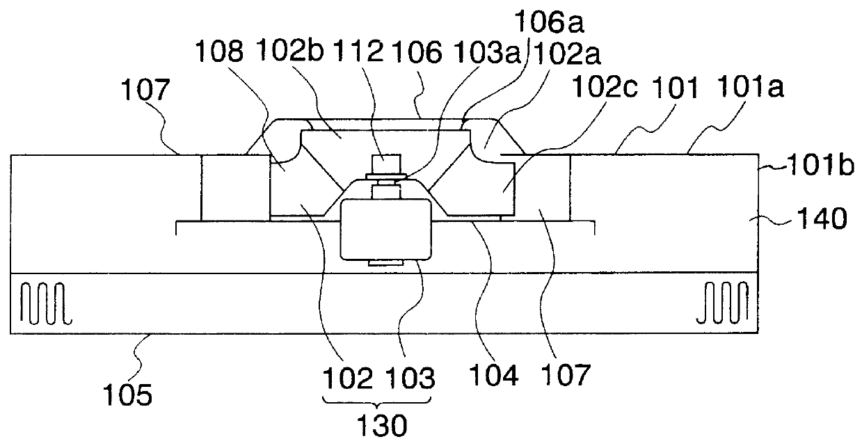
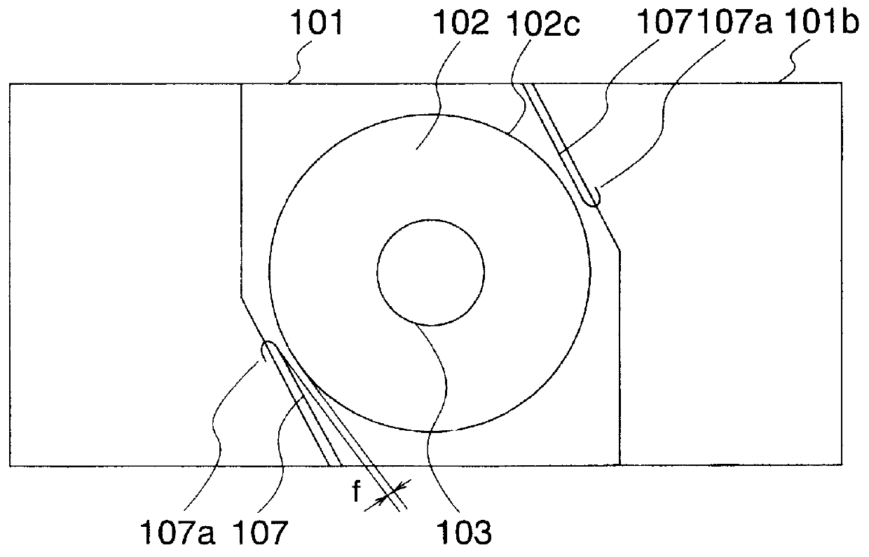
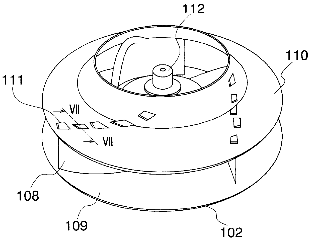
Exemplary embodiments of the present invention will now be explained with reference to FIGS. 1 to 19. As disclosed in FIGS. 1 and 2, an air cleaner in this embodiment has a fan 130, a filter 105 and a housing 101 for accommodating the fan 130 and the filter 105. The fan 130 includes a vane-wheel 102, and a motor 103 to rotate the vane-wheel 102. A motor base 104, configured as a supporting plate, supports the motor 103 in the housing 101. The housing 101 has an upper wall 101a, side walls 101b and an opening at its bottom portion for installing the filter 105. The housing 101 ...


PUM

PropertyMeasurementUnit
Poweraaaaaaaaaa
Volumeaaaaaaaaaa
Weightaaaaaaaaaa

Abstract

An air cleaner includes a housing having an upper wall and side walls, an air filter mounted with respect to the housing, a fan including a vane-wheel having a plurality of vanes, a supporting plate extending substantially between at least two side walls for supporting the fan. An air flow directional member directs an air flow output from the fan. The vane is formed to have a winglike cross-section, and the vane-wheel includes not more than four vanes. The vane-wheel has a base plate and a shroud. Each of the base plate and the shroud is formed to have a reinforcement portion on its circumference. A U-shaped balance weight is attached to a flattened portion formed on the curled portion. The air cleaner of the present invention can reduce noise and vibration and improve efficiency of the fan.

Description

BACKGROUND OF THE INVENTION1. Technical Field of the InventionThe present invention generally relates to an air cleaner, and more specifically, relates to an air cleaner installed within a ceiling of a clean room used for manufacturing elements or devices such as semiconductor or liquid crystal arrangements, wherein the air cleaner has a vane-wheel capable of improving a fan efficiency and capable of decreasing a noise and a vibration.2. Description of Related ArtAn example of a construction of an air cleaner in a related art is explained referring to FIGS. 20-22. As is disclosed in FIG. 20, the air cleaner 20 in the related art has a fan including a vane-wheel 10 and a motor 6 for rotating the vane-wheel 10, a filter 24 and a housing 21 for accommodating the fan and the filter 24. A motor base 7 supports the motor 6 in the housing 21. The housing 21 has an air inlet 26 at its upper plate, and has an opening at its bottom portion for installing the filter 24. A filter frame 28 is di...

Claims


Application Information

Patent Timeline
IPC IPC(8): F04D29/66F04D29/30F24F3/16F24F1/00F24F8/80F24F8/108
CPCF04D29/30F04D29/662F04D29/281F24F3/1603F24F2001/0096F24F1/0071F24F8/10F24F8/108F24F8/80F24F7/06
Inventor ISHIKAWA, TOMINORITOYAMA, YUJIYOKOYAMA, MAKOTOTAKADA, YOSHIHIROHONMA, KEIICHIKAWASAKI, OSAMUINOUE, MASAYOSISUGAI, KAZUNARITAZAWA, JUN
Owner HITACHI LTD
Why Eureka
Try Eureka