Drainage catheter anchor locking mechanisms

a technology of locking mechanism and draining catheter, which is applied in the field of catheters, can solve the problems of limiting the possible locations of securing the locking mechanism, patient skin irritation, and potential for severe infections

Inactive Publication Date: 2000-12-12
BOSTON SCI SCIMED INC
View PDF11 Cites 73 Cited by
  • Summary
  • Abstract
  • Description
  • Claims
  • Application Information

AI Technical Summary

Problems solved by technology

Also these catheters generally have side ports at the distal end that can be inadvertently drawn into the abdominal cavity creating potential for severe infections when the catheter is inserted for bladder treatment.
This...

Method used


Image

  • Drainage catheter anchor locking mechanisms
  • Drainage catheter anchor locking mechanisms
  • Drainage catheter anchor locking mechanisms

Examples


Embodiment Construction

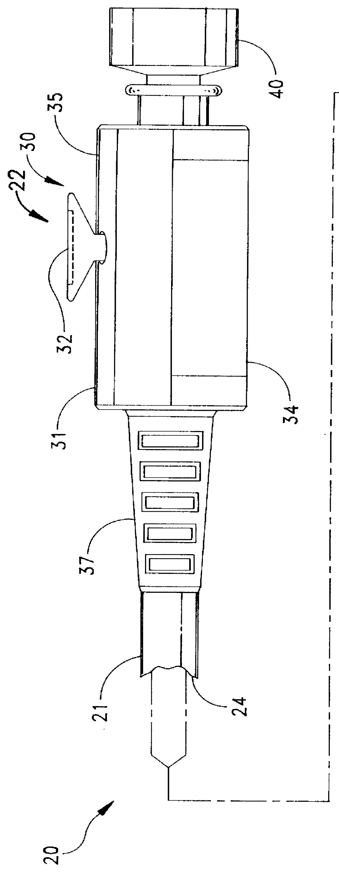
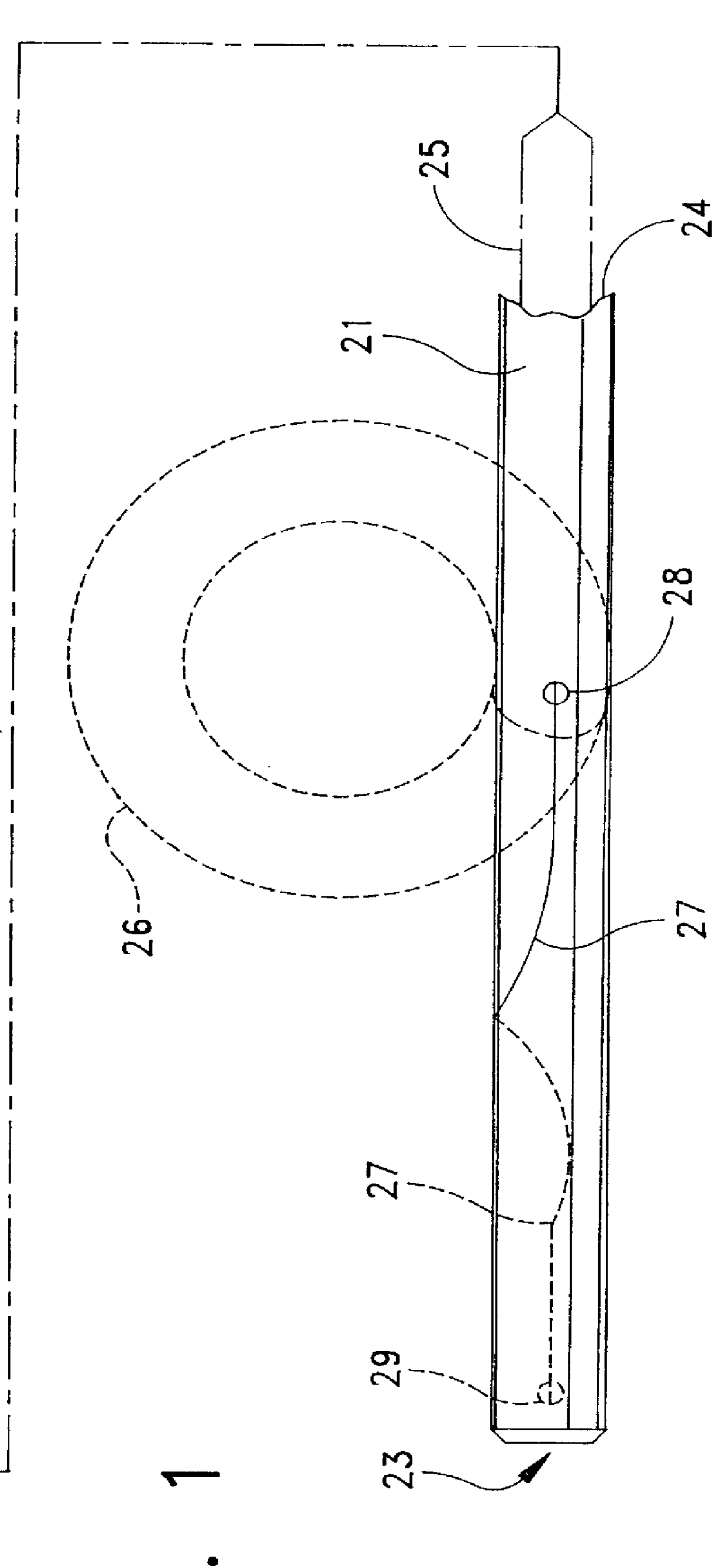
FIG. 1 depicts a catheter 20 with a radially flexible tube 21 that extends between a proximal end 22 and a distal end 23. A lumen 24 extends through the tube 21 and carries a flexible link 25 in the form of one or more suture threads. A two-part suture thread 25 is shown in FIG. 1. As shown by the solid lines in FIG. 1, the tube 21 extends along an axis when it is inserted and deflects into a pigtail loop 26 as shown by the dashed lines in FIG. 1 when a cannula or other straightening implement is removed from the lumen 24. As known, the pigtail loop 26 constitutes one form of an anchor.

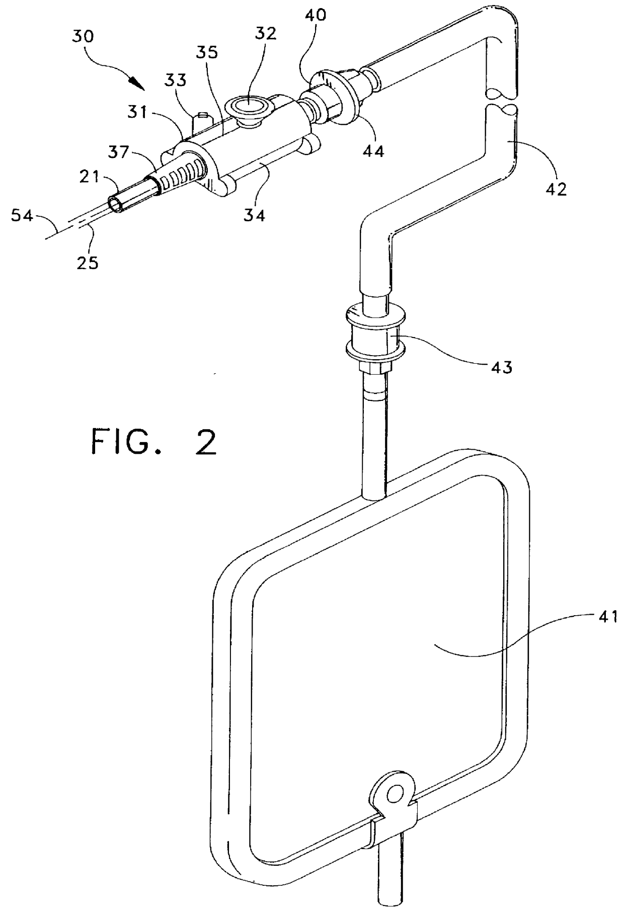
A distal end portion 27 of the suture thread 25 extends through a draw port or aperture 28 displaced from the distal end 23 and a draw port 29 or other connection at the distal end 23. Typically a single suture thread has its mid point located at the distal draw port 29 with the resulting two strands or ports being led proximally through the lumen 24. A locking mechanism 30 constructed in accordance w...


PUM


Abstract

A drainage catheter includes a tubular member with an anchor at a distal end and suture threads extending from the anchor to the proximal ends of the tubular member. A locking mechanism attaches to the proximal end of the tubular member and includes a body with an extension of the lumen. A displaceable body in the locking mechanism body attaches to the proximal end of the sutures to control the amount of slack or tension in the suture threads. An extension of that displaceable body lies externally of the locking mechanism body to enable the operation of the displaceable body without handling the suture threads.

Description

1. Field of the InventionThis invention generally relates to the field of catheters and more particularly to a catheter having a mechanism for retaining a distal end of the catheter in a predetermined configuration.2. Description of Related ArtThere are a variety of therapies or treatment modalities that require a catheter with a distal anchor or the like to retain the catheter in position. One particular application involves catheters used for drainage purposes. For example, procedures for the suprapubic catheterization of the bladder to drain the bladder after surgery or when the genitourinary system is plugged by an obstruction. Procedures using other percutaneously inserted catheters are also used to drain the kidney or biliary system as well as to drain abscesses, other sites of fluid collection and other viscera. Still other procedures use percutaneously inserted catheters as gastrostomy feeding tubes.Generally these catheters are introduced into a patient through a large hypo...

Claims


Application Information

Patent Timeline
IPC IPC(8): A61M25/00A61M25/01A61M25/02A61M25/04
CPCA61M25/0041A61M25/0136A61M25/0133A61M25/0105A61M25/0113A61M2025/09125A61M25/04A61M2025/0163
Inventor AMOS, JR., RAYMOND GEORGECOLVIN, BOYD ALLENNISHTALA, SRINIVASPERKINS, D. H.SMITH, JEFFEREY CARL
Owner BOSTON SCI SCIMED INC
Why Eureka
Try Eureka