Interferometer system and method for lens column alignment

a technology of interferometer and lens column, applied in the field of projection exposure system, can solve the problems of not providing accurate alignment information, interfering with each other, and not properly detecting all alignment problems

Inactive Publication Date: 2000-12-12
NIKON CORP
View PDF10 Cites 56 Cited by
  • Summary
  • Abstract
  • Description
  • Claims
  • Application Information

AI Technical Summary

Problems solved by technology

As the beams travel back through the beam splitter they interfere with each other.
Charges in beam 21, however, may not provide accurate information for alignment because of the sensitivity of lens column 16 to thermal expansion and displacement.
More particularly, because conventional alignment procedures use only one side of lens column 16, all of the alignment problems are not properly detected.
Accordingly, the adjustment of stage 14 in relation to lens column 16 is often inaccurate and, as such, results in errors in the projection of the image of the pattern onto the substrate on stage 14.
Typically, adjusting stage 14 results in vibration throughout the projection exposure apparatus.
Accordingly, adjustment of stage 14 in relation to lens column 16 is often inaccurate and results in errors in the projection of the image of the pattern onto the substrate on stage 14.

Method used


Image

  • Interferometer system and method for lens column alignment
  • Interferometer system and method for lens column alignment
  • Interferometer system and method for lens column alignment

Examples


Embodiment Construction

)

Reference will now be made in detail to an embodiment of the invention, examples of which are illustrated in the accompanying drawings.

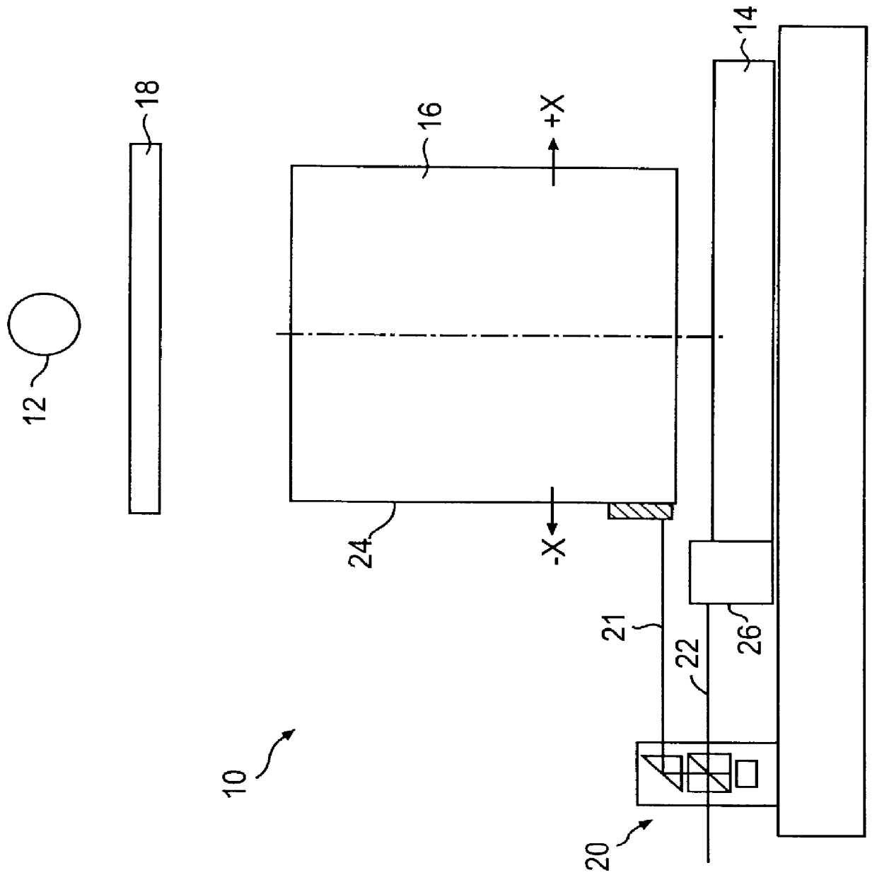
In accordance with the invention, there is provided a projection exposure apparatus and method for transferring an image of a pattern formed on a mask through a lens column along an optical axis perpendicular to a substrate, onto the substrate. Precise alignment of the substrate with the optical axis is achieved by the present invention, which detects proper alignment using one or more interferometers that pass at least one beam of light to an opposite side of the lens column.

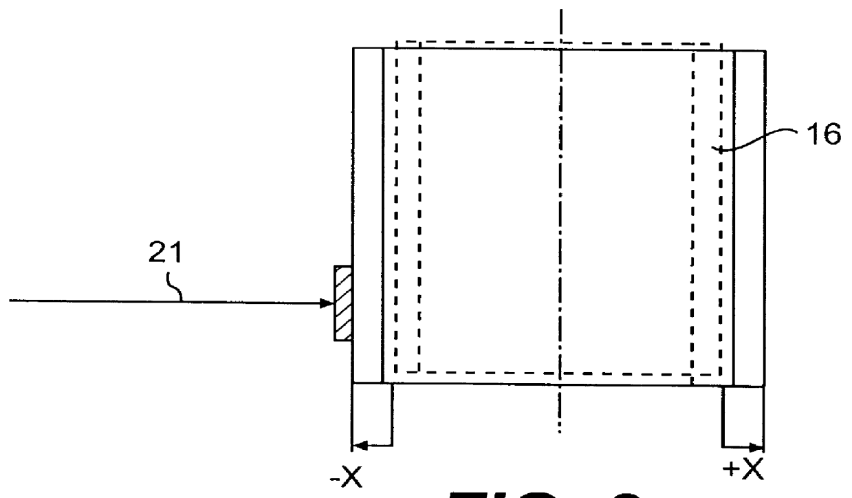
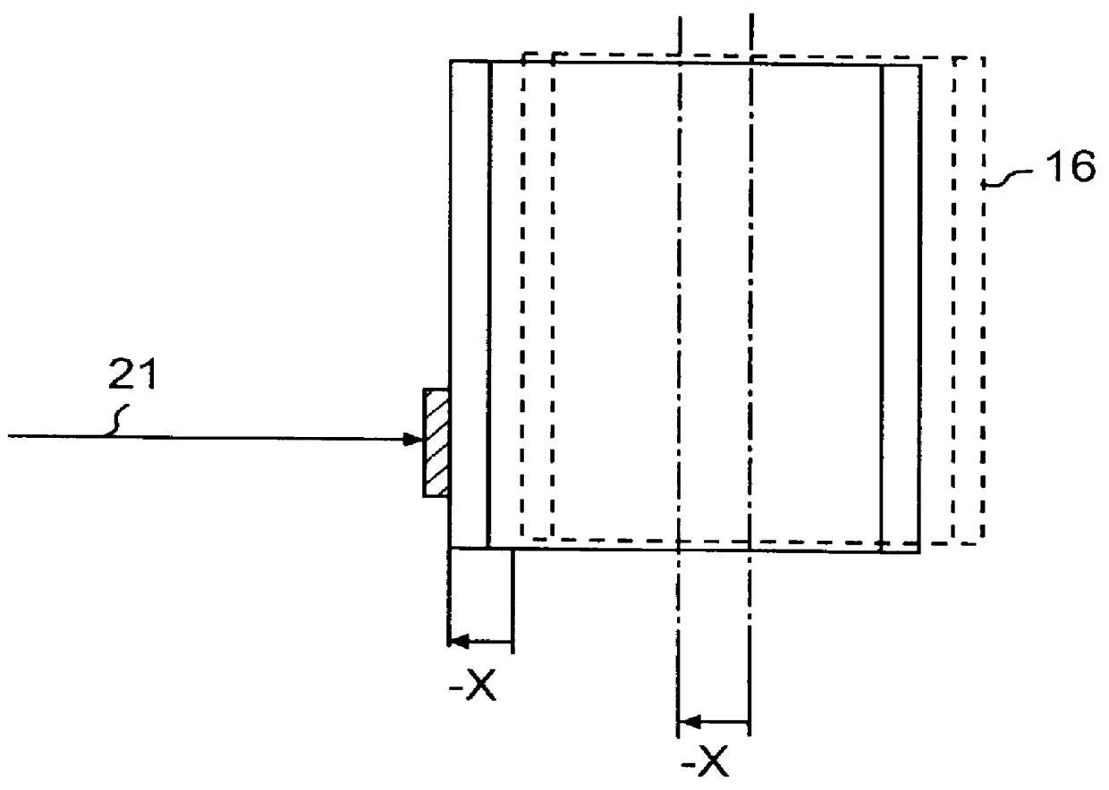
The projection exposure apparatus of the present invention includes a projection optical system, one or more interferometers, and a control device. The one or more interferometers are oriented such that a plurality of beams are created. Each beam has a respective path, the length of which changes in response to a change in a dimension of the lens column along the path of the be...


PUM

PropertyMeasurementUnit
photosensitiveaaaaaaaaaa
optical axisaaaaaaaaaa
opticalaaaaaaaaaa

Abstract

A projection exposure apparatus and method aligns a substrate with an optical axis of a lens column using one or more interferometers, mirrors, and a control device. The lens column projects a pattern from a mask onto the substrate. The optical axis of the lens column is perpendicular to the substrate. To ensure precise alignment of the lens column and the substrate, the one or more interferometers use a plurality of beams having respective paths, the lengths of which change in response to movement of the optical axis. In response to the detected changes of the interferometer beams, a control device adjusts the position of the stage so that the substrate is aligned with the optical axis of the lens column.

Description

A. Field of the InventionThe present invention relates generally to a projection exposure system for transferring an image of a pattern onto a substrate, such as a semiconductor wafer. More particularly, the present invention relates to a projection exposure apparatus and method that provides enhanced precision in the alignment of a projection optical system and the substrate.B. Description of the Prior ArtSemiconductor fabrication requires precise alignment of an optical system with a substrate in order to produce extremely detailed circuitry on the substrate. FIG. 1 illustrates a conventional projection exposure apparatus 10, which includes a light source 12, a stage 14, a lens column 16, a mask 18, and an interferometer 20. Light source 12 illuminates mask 18, causing a pattern from the mask to be projected through lens column 16. Lens column 16 projects the pattern onto a photosensitive substrate on stage 14. The optical axis of lens column 16 is indicated by the broken line dow...

Claims


Application Information

Patent Timeline
Patent Type & Authority Patents(United States)
IPC IPC(8): G03F7/20G01B9/02G03F9/00H01L21/027
CPCG03F7/70241G03F7/709G03F7/70725G03F7/70258
Inventor INOUE, FUYUHIKO
Owner NIKON CORP
Why Eureka
Try Eureka