Electronic card

a technology of electronic cards and cards, applied in the direction of casings/cabinets/drawers, electrical apparatus construction details, casings/cabinets/drawers, etc., can solve the problems of difficulty in maintaining sufficient rigidity of such structures to withstand flexing

Inactive Publication Date: 2000-12-12
FCI AMERICAS TECH LLC
View PDF8 Cites 12 Cited by
  • Summary
  • Abstract
  • Description
  • Claims
  • Application Information

AI Technical Summary

Problems solved by technology

However, there are difficulties experienced in having such structures maintain sufficient rigidity to withstan

Method used


Image

  • Electronic card
  • Electronic card
  • Electronic card

Examples


Embodiment Construction

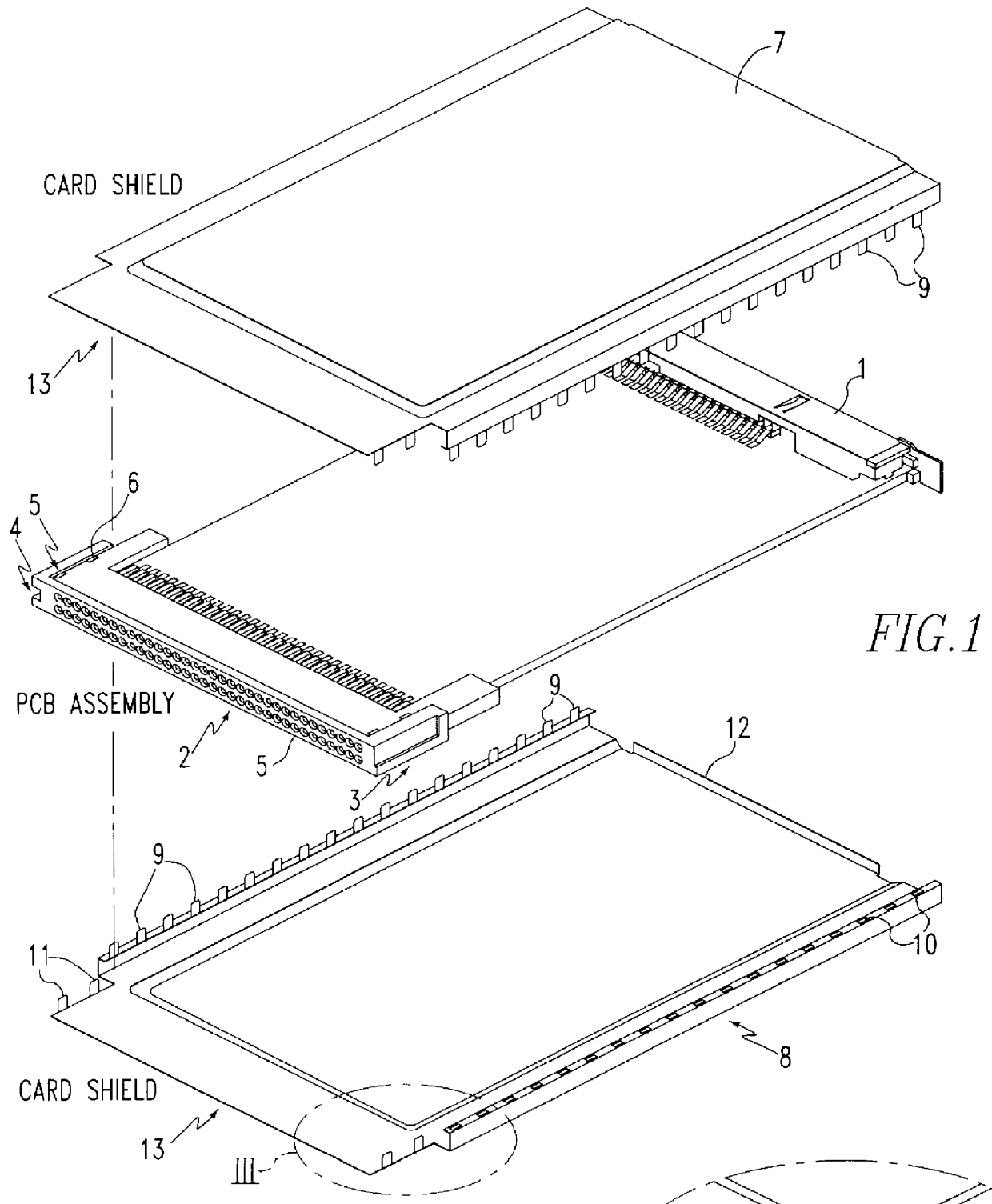
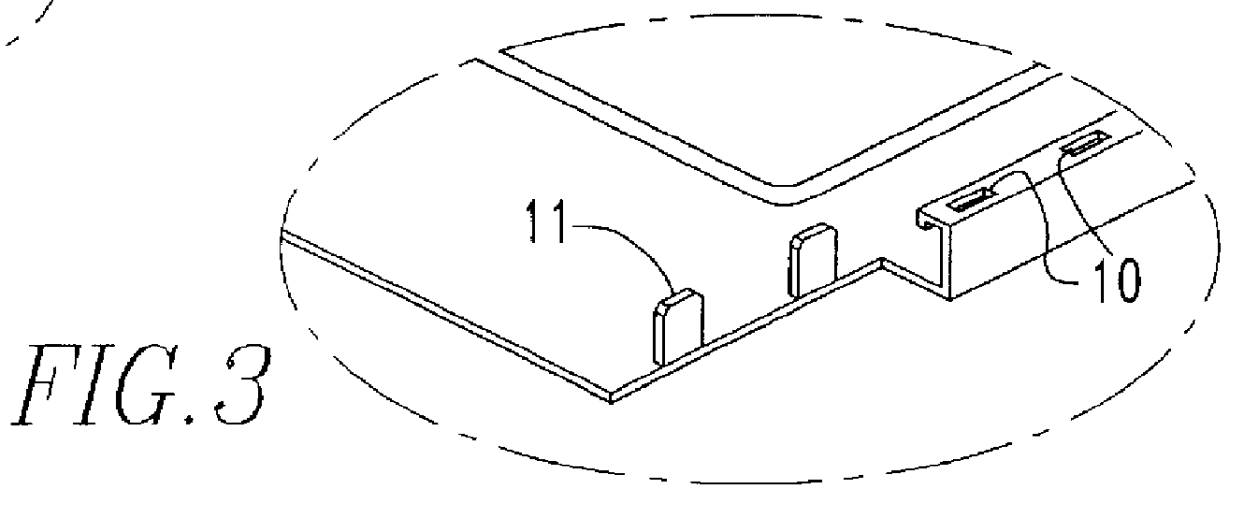
The card thickness on the 68 pos connector side is for a short length 3.3 mm; subsequently this increases for the substantial card length to 5 mm thickness (with depressed portion, not shown, to allow for card sticker thickness), returning to the 3.3 mm at the I / O connector side. The basic point being made with FIG. 2 is the deep-draw dimension of 0.75 with stainless steel material of 0.2 mm thick with the specified shield flatness. In addition, the importance of the card aesthetics dictate outer surface which is devoid of grease or scratches, flat within spec, and no "oil-canning" effects. It is essential to understand the constraints imposed by above restrictions in the deep-draw stamping process of these shields. This is the subject of discussion in this novelty. For deep-draw, other problems occur due to local double bending operation and flaws due to material necking and local change in material thickness resulting from this operation. Besides final product dimensional aspects,...


PUM

PropertyMeasurementUnit
Fractionaaaaaaaaaa
Fractionaaaaaaaaaa
Fractionaaaaaaaaaa

Abstract

Disclosed is an electronic card comprising a printed circuit board interposed between card shields having edges. Tabs on an edge of one shield engage recesses on the edge of the other shield. The jointed shields of the card provide high levels of rigidity, sufficient to exceed applicable bending and torsional resistance specification. Adequate rigidity is thereby provided. Also included is an I/O connector grounded without a separate ground contact and shielded over its length. The tabs include an arcuate member having a medial oblique projection which engages a ledge of the other shield near the recess. A frame bar is interposed between the shields. Also included is an "oil can" resistant shield in which a deep-draw recess is peripherally surrounded by a groove.

Description

1. Field of the InventionThe present invention relates to electronic cards and more particularly to exterior shells for such cards.2. Brief Description of Prior DevelopmentsElectronic cards are widely used, especially for adding capacity and / or functionality to personal computers. The Personal Computer Memory Card International Association (PCMCIA) has established standards for such cards, and has categorized them as type I, type II and type III cards.Previously cards have employed cover shields latched and / or adhesively fixed to an intermediate frame and covers laser welded or ultrasonically welded together. More recent cards employ metal shields that are directly fixed together, without a frame. However, there are difficulties experienced in having such structures maintain sufficient rigidity to withstand flexing, bending and tension forces which would be expected to be placed on it in the course of ordinary use. There is, therefore, a need for an electronic card which avoids the ...

Claims


Application Information

Patent Timeline
IPC IPC(8): H05K5/02
CPCH05K5/0269H05K5/0273Y10T29/49002
Inventor GERRITS, ANTONIUS H. J.PIGMANS, PAULUS J. M.ALST, WIM VANPOTTERS, PAUL J. M.
Owner FCI AMERICAS TECH LLC
Why Eureka
Try Eureka