Bending apparatus

a technology of bending apparatus and bending pipe, which is applied in the field of bending apparatus, can solve the problems of increasing the number of bent pipes, increasing the manufacturing cost of bent pipes, and increasing the thickness of walls, and achieves the effect of high-quality bending

Active Publication Date: 2006-03-16
SANOH IND CO LTD
View PDF7 Cites 21 Cited by
  • Summary
  • Abstract
  • Description
  • Claims
  • Application Information

AI Technical Summary

Benefits of technology

[0017] Using this bending apparatus of the present invention, the wrinkle removing die restrains the region around the inside wall of

Problems solved by technology

However, when a bend with a tight bending radius is attempted with the aforementioned conventional bending apparatus, the outside wall 54a in the bending region 54 formed in the pipe 50 will be elongated, and there will be problems with flattening of the pipe and the wall thickness becoming extremely thin as shown in FIG. 6.
However, the aforementioned post-bending pipe correcting operat

Method used


Image

  • Bending apparatus
  • Bending apparatus
  • Bending apparatus

Examples


Embodiment Construction

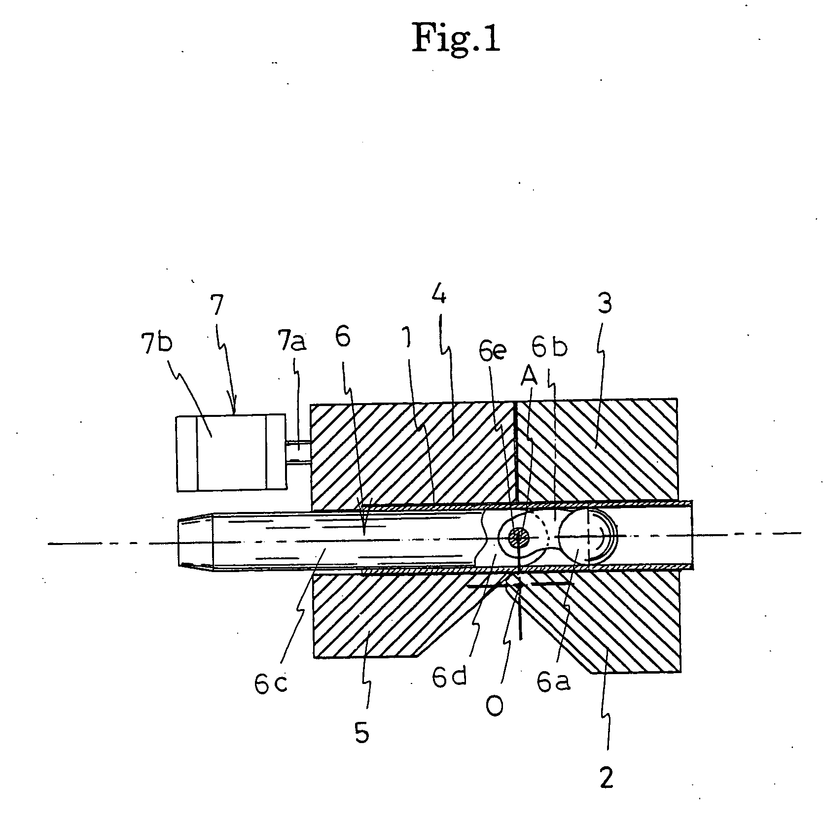
[0025] A preferred embodiment of the bending apparatus of the present invention will be described in detail below while referring to the drawings.

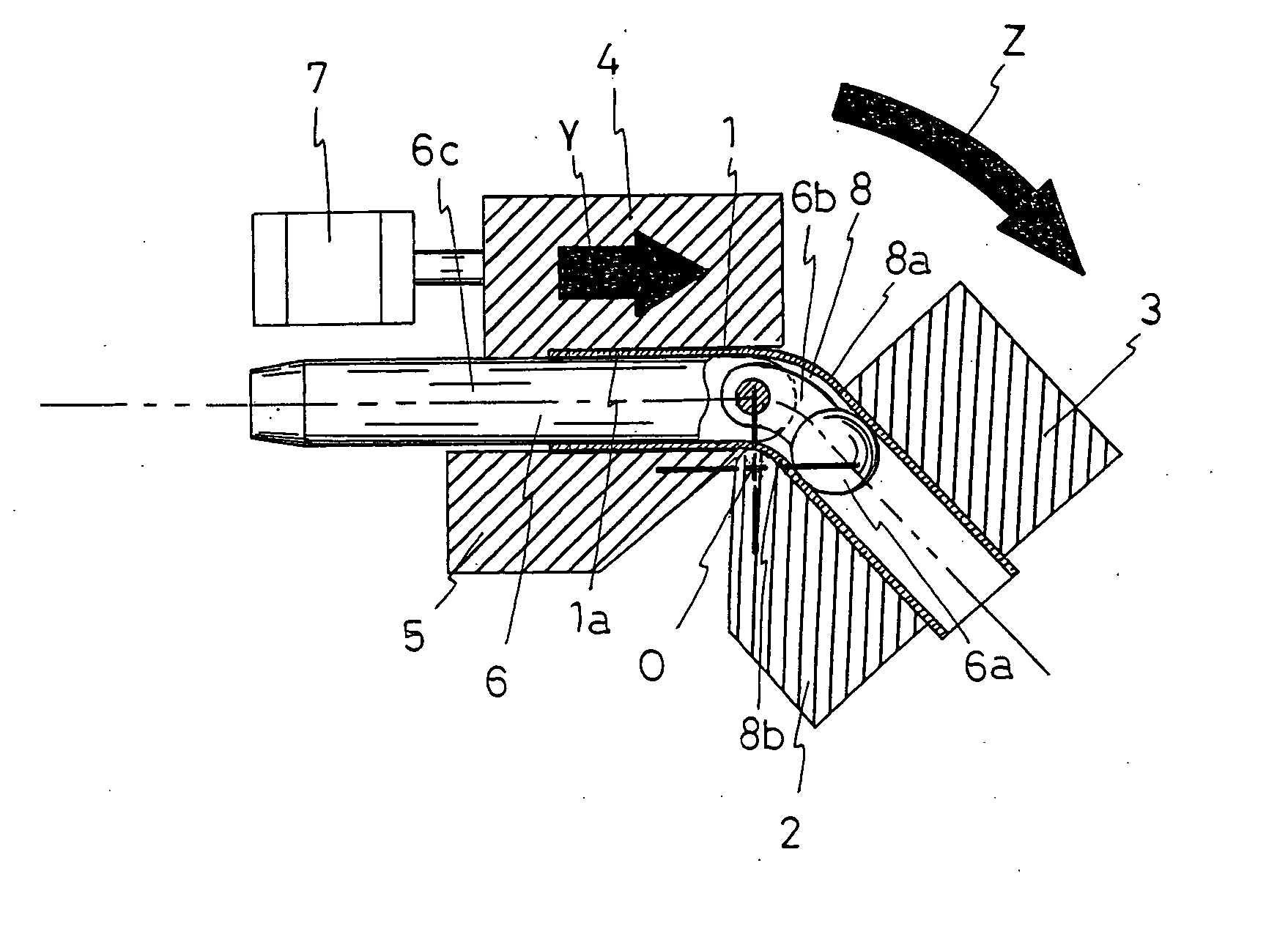
[0026] As shown in FIG. 1, the bending apparatus of the present invention has a pipe 1 bending die 2, a clamping die 3 which sandwiches the pipe 1 together with bending die 2 and rotates together with the bending die 2, and a pressure die 4 which presses the pipe 1, and furthermore, in this preferred embodiment, a pipe 1 wrinkle removing die 5 is established at a position opposite to the pressure die 4.

[0027] Note, although omitted from the drawings, the surfaces of the bending die 2 and the clamping die 3 have semicircular grooves which match the shape of the pipe 1, and the surfaces of the pressure die 4 and the wrinkle removing die 5 also have similar grooves.

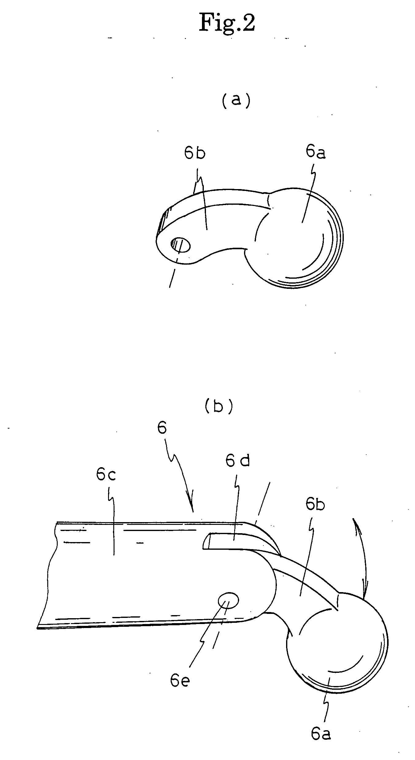
[0028] Furthermore, a metal core 6 which maintains the shape of the bending region of the pipe 1 is inserted into place from one end of the pipe 1. As described in FIG. 2, this ...


PUM

PropertyMeasurementUnit
Pressureaaaaaaaaaa
Shapeaaaaaaaaaa

Abstract

A bending apparatus which can bend pipes and obtain as small curvature as possible without flattening or buckling easily occurring in the bending region. The bending apparatus comprises a bending die for a pipe, a clamping die which rotates together with the bending die while clamping the pipe, a pressure die which hold down the pipe, and a metal core which is inserted into the pipe and maintains the shape of the bending region, wherein the metal core is a spherical metal core rotatably supported by an arch shaped arm on the leading end of a core holder.

Description

BACKGROUND OF THE INVENTION [0001] 1. Field of the Invention [0002] The present invention relates to a bending apparatus, and more particularly to a bending apparatus suitable for bending pipes with a small bending radius. [0003] 2. Description of the Related Art [0004] The use of smaller components in automobile engine compartments and cooling apparatus have increased in recent years, and demand is increasing for metal pipes which are bent to a small bending radius, for instance to a bending radius which is smaller than the diameter of the pipe, in order to connect between components which are tightly arranged. [0005] As shown in FIG. 5 and FIG. 6, a conventional bending apparatus bends pipe 50 to a prescribed angle by interposing the pipe 50 between a bending die 51 and a clamping die 52, holding down the pipe 50 using a pressure die 53, and in this condition, rotating the bending die 51 and the clamping die 52 with the center O of the bend as the center of rotation. [0006] Howeve...

Claims


Application Information

Patent Timeline
IPC IPC(8): B21D9/05
CPCB21D9/05
Inventor NAKAZATO, KAZUHIKO
Owner SANOH IND CO LTD
Why Eureka
Try Eureka