Integrated optical circuit

a technology of integrated optical circuits and optical elements, applied in the direction of optical elements, instruments, optical waveguide light guides, etc., can solve the problems of adding extra complexity and expense to the manufacturing process

Inactive Publication Date: 2000-12-19
BOOKHAM TECH
View PDF12 Cites 81 Cited by
  • Summary
  • Abstract
  • Description
  • Claims
  • Application Information

AI Technical Summary

Benefits of technology

According to a first aspect of the invention, there is provided an integrated optical circuit for use in a fibre optic gyroscope which senses rotation rates by determining a phase shift due to the Sagnac Effect between light beams travelling around an optical fibre sensing loop in opposite directions, the circuit being provided on a silicon-on-insulator chip comprising a layer of silicon separated from a substrate by an insulating layer, the circuit comprising: rib waveguides formed in the silicon layer for receiving light from a light source and t

Problems solved by technology

However, the design of these has been such as to include non-silicon passive functional elements.
This adds extra complexity and expense to the manufactur

Method used


Image

  • Integrated optical circuit
  • Integrated optical circuit
  • Integrated optical circuit

Examples


Embodiment Construction

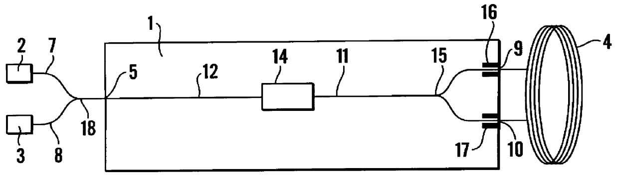
The fibre optic gyroscope illustrated in FIG. 1 comprises an integrated optical circuit, fabricated on a silicon-on-insulator chip 1. This comprises an upper layer of silicon separated from an underlying layer of silicon, by an insulating layer, such as silicon dioxide. Such a substrate preferably comprises an upper layer of silicon 3 to 15 microns thick separated from the underlying silicon layer by a layer of silicon dioxide at least 0.1 microns thick and preferably at least 0.3 microns thick. Such substrates are readily commercially available. References in the following description to the silicon layer refer to the upper layer described above.

The integrated optical circuit 1 connects together a light source 2, a light detector 3, and an optical fibre loop 4, which forms the sensing element of the gyroscope.

The integrated optical circuit 1 comprises first and second fibre connectors 5 and 6 for receiving optical fibres 7 and 8 transmitting light to and from the light detector 3 a...


PUM


Abstract

An integrated optical circuit for use in a fibre optic gyroscope which senses rotation rates by determining a phase shift due to the Sagnac Effect between light beams travelling around an optical fibre sensing loop (4) in opposite directions, the circuit being provided on a silicon-on-insulator chip comprising a layer of silicon separated from a substrate by an insulating layer, the circuit comprising: rib waveguides (11) formed in the silicon layer for receiving light from a light source (2) and transmitting light to a light detector (3), fibre optic connectors (9) in the form of grooves etched in the silicon layer for receiving the respective ends of the optical fibre sensing loop (4); rib waveguides (11) formed in the silicon layer for transmitting light to and from said fibre optic connectors (9) so as to direct light beams in opposite directions around the sensing loop (4) and receive light beams returning therefrom, phase determining means and (13,17,31) integrated in silicon layer for determining a phase shift between the light beams returning from the sensing loop (4).

Description

This invention relates to an integrated optical circuit for use in a fibre optic gyroscope.Fibre optic gyroscopes for measuring rotation rates based on the Sagnac effect are known. When light traverses an optic fibre loop which is rotating about an axis perpendicular to its plane, the optical transmit time of the light varies in dependence on the loop's rotation rate. For two optical signals traversing the loop in opposite directions the Sagnac phase difference between them is proportional to the rotation rate.Integrated optical circuits for use with such fibre optic gyroscopes have been proposed, for example, in U.S. Pat. No. 5,194,917. However, the design of these has been such as to include non-silicon passive functional elements. This adds extra complexity and expense to the manufacturing process due to extra alignment and fabrication stages required to try to avoid or minimise problems due to material mis-match and / or coupling losses.The present invention seeks to avoid or redu...

Claims


Application Information

Patent Timeline
IPC IPC(8): G01C19/72G02B6/12G02F1/01G02F1/025G02B6/28
CPCG01C19/722G02B6/12004G02F1/025G02B2006/2865G02B2006/12119G01C19/725G01C19/728
Inventor RICKMAN, ANDREW GEORGEHARPIN, ARNOLD PETER ROSCOEPECHSTEDT, RALF-DIETERMCKENZIE, JAMES STUART
Owner BOOKHAM TECH
Why Eureka
Try Eureka