

Hydraulic brake system for motor vehicles
a brake system and hydraulic technology, applied in the direction of braking systems, machines/engines, rotary/oscillating piston pump components, etc., can solve the problems of insufficient filling of the brake fluid supply container, inability to feed air into the system, and inability to achieve the effect of reducing the number of cylinders
- Summary
- Abstract
- Description
- Claims
- Application Information
AI Technical Summary
Benefits of technology
Problems solved by technology
Method used
Image

Examples
Embodiment Construction
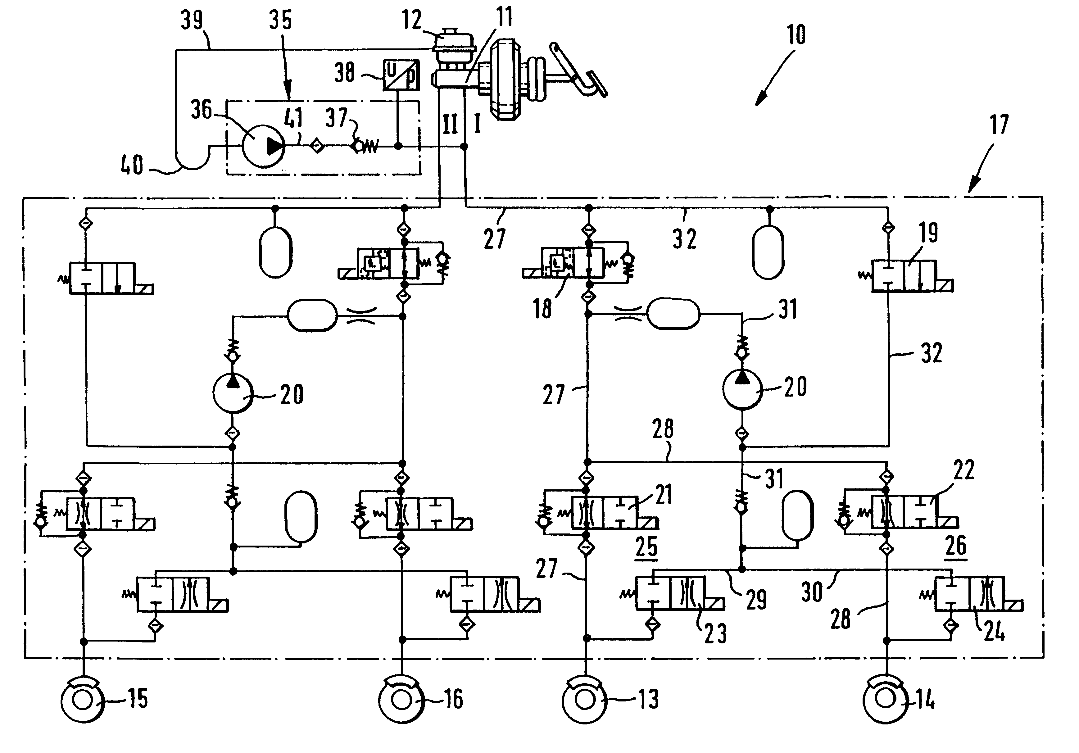
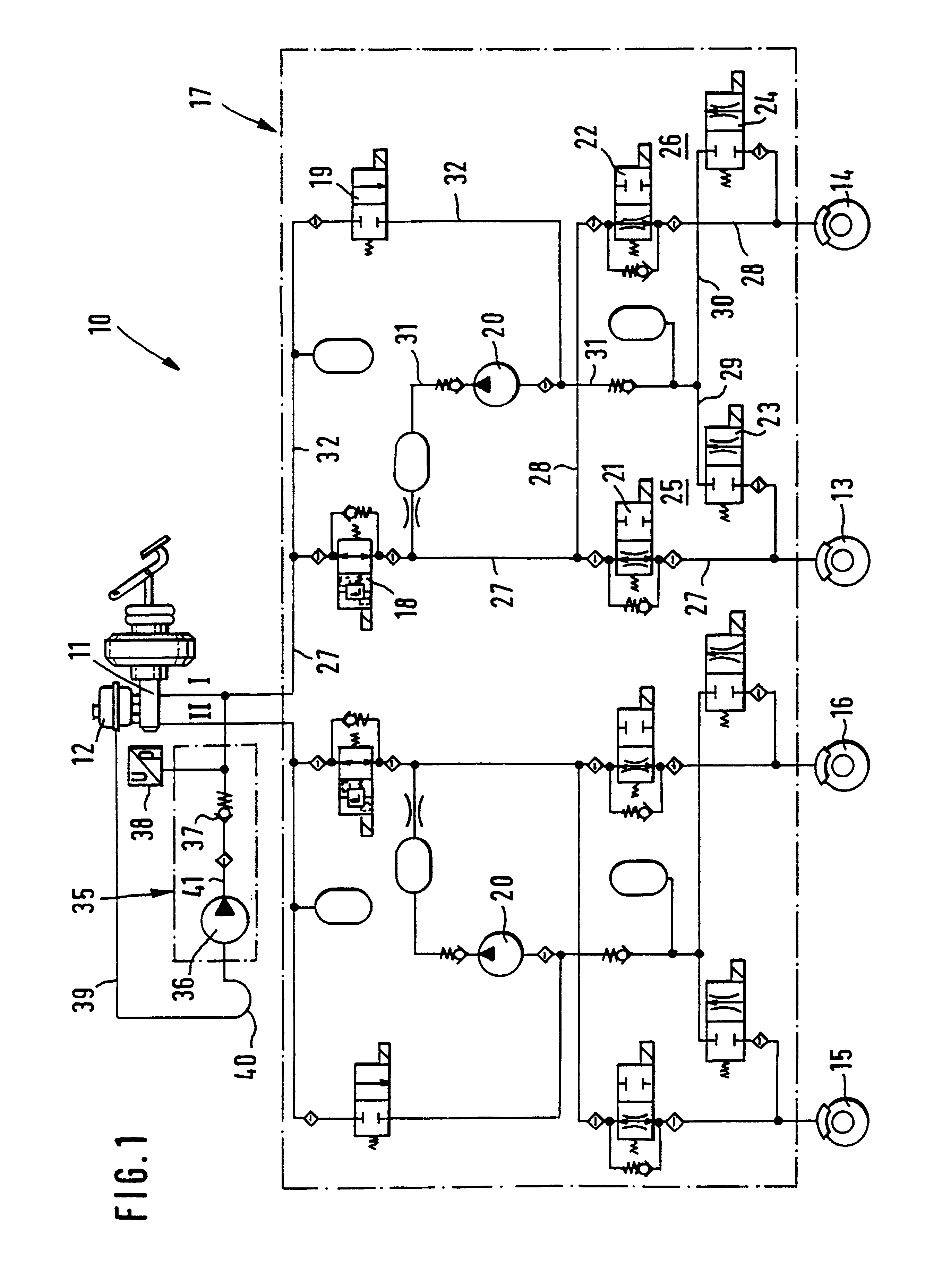
A hydraulic brake system 10 for motor vehicles, schematically shown in FIG. 1, has a dual-circuit, pedal-actuatable master cylinder 11 with a supply container 12 for brake fluid. A first brake circuit I assigned to the wheel brakes 13, 14 of a front axle of the vehicle is connected to the master cylinder 11; a second brake circuit II of the master cylinder 11 communicates with wheel brakes 15, 16 of the rear axle of the vehicle. Elements of the brake system 10, which in accordance with the circuit diagram shown in FIG. 1 are disposed between the master cylinder 11 and the wheel brakes 13-16 in the brake circuits I and II, are combined in a hydraulic unit 17.
As will be described below in terms of brake circuit I, these elements include a shutoff valve 18 with a pressure limiting function; a charge valve 19; a high-pressure pump 20; and pressure buildup valves 21, 22 and pressure reduction valves 23, 24 of pressure modulating devices 25 and 26 that are assigned to the wheel brakes 13 ...
PUM
 Abstract
Description
Claims
Application Information