Seal arrangement for an electric motor

a technology of sealing arrangement and electric motor, which is applied in the direction of rigid support of bearing unit, mechanical energy handling, mechanical apparatus, etc., can solve the problems of relative speed between the sealing element and the rotating element, oil mist-lubricated motor bearing, and bearing installation of sealing anti-friction bearing on the electric motor sha

Inactive Publication Date: 2001-01-09
RELIANCE ELECTRIC TECH
View PDF18 Cites 58 Cited by
  • Summary
  • Abstract
  • Description
  • Claims
  • Application Information

AI Technical Summary

Problems solved by technology

A difficulty which arises in oil mist-lubricated motor bearings involves the escape of oil mist into the motor housing and outwardly into the atmosphere surrounding the motor.
Even where seals are employed these are typically provided for preventing the ingress of contaminants and moisture into the bearing cavity, often inadvertently facilitating the conveyance of oil mist from the bearing cavity into the motor enclosure.
Other difficulties in sealing anti-friction bearings installed on electric motor shafts arise from the relative speeds between the sealing elements and the rotating elements, typically the shaft itself.
In particular, while certain sealing arrangements may be employed to isolate inner bearing cavities from ambient air and from the inner volume of the electric motor housings, the use of such seals is typically limited by the relative surface velocity of the rotating and non-rotating elements.
However, where such velocities become excessive, the seal life may be significantly reduced due to heating caused by friction between the seal and the rotating member.
Moreover, depending upon the motor design and its rated speed, the same sealing arrangements may not be applicable due to the increased speed of the motor (e.g., two-pole speeds of 3600 rpm in 60 Hertz electrical supply systems).

Method used


Image

  • Seal arrangement for an electric motor
  • Seal arrangement for an electric motor
  • Seal arrangement for an electric motor

Examples


Embodiment Construction

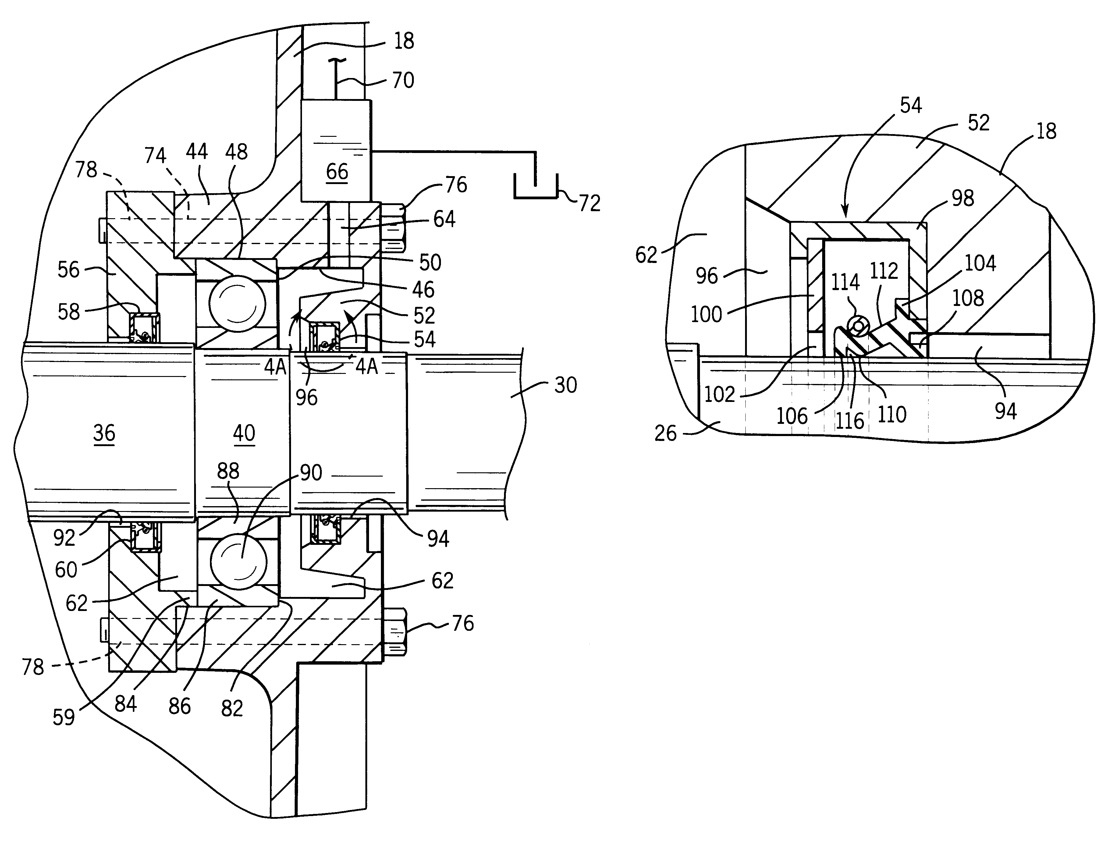
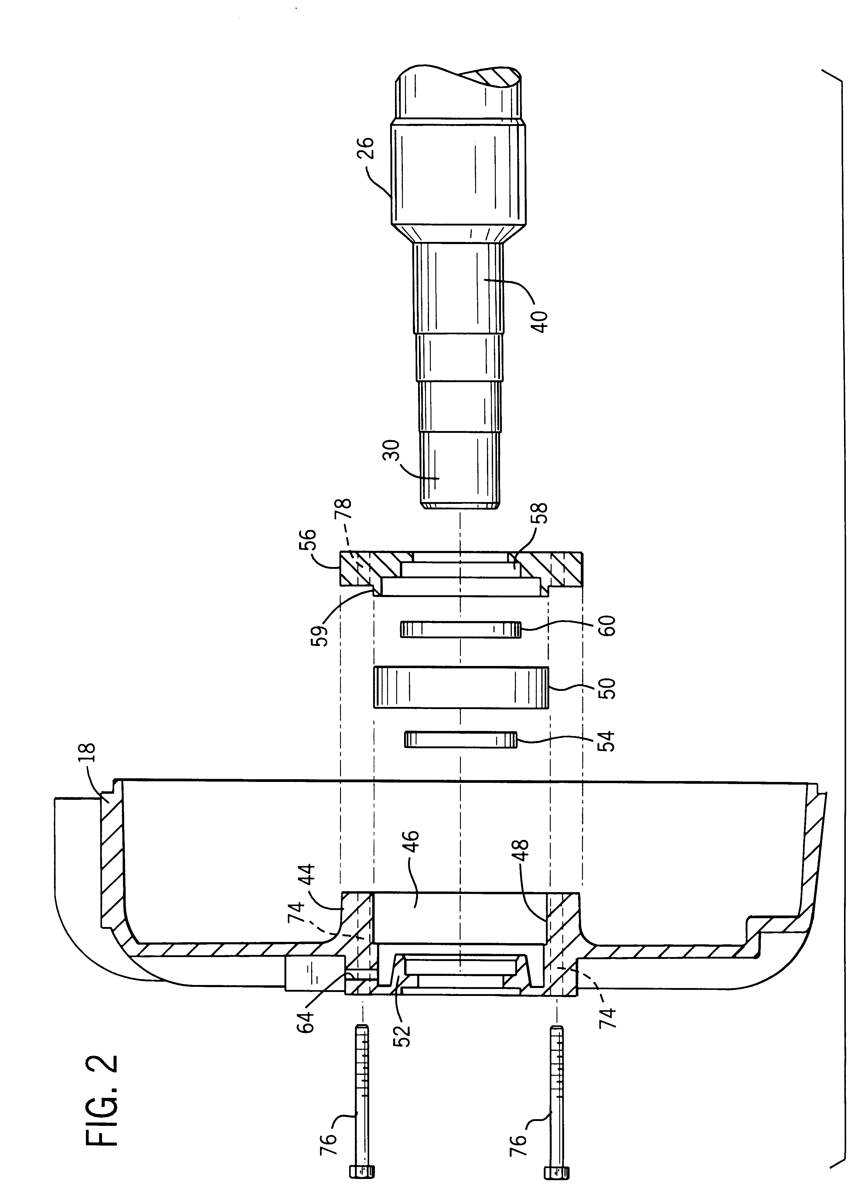
Turning now to the drawings, and referring first to FIG. 1, a diagrammatical sectional view of an electric motor is illustrated including sealing arrangements for a pair of bearing sets. The electric motor, designated generally by the reference numeral 10, includes a stator assembly 12 in which a rotor assembly 14 is rotatably positioned. Stator assembly 12 is lodged within a central housing section 16 of the electric motor in accordance with known techniques. Housing 16 is bounded by a front end bracket 18 and a rear end bracket 20. As will be appreciated by those skilled in the art, front and rear end brackets 18 and 20 provide support for a front bearing and seal assembly 22, and a rear bearing and seal assembly 24, respectively. Assemblies 22 and 24 will be described in greater detail below. It should be noted that details of the stator and rotor construction have not been represented in FIG. 1 for the sake of clarity.

In the embodiment illustrated in the Figures, motor 10 is a t...


PUM

PropertyMeasurementUnit
pressureaaaaaaaaaa
poweraaaaaaaaaa
electric poweraaaaaaaaaa

Abstract

A technique is provided for sealing a bearing cavity in a rotating machine such as an electric motor. The bearing cavity is defined by annular elements on either side of an antifriction bearing set. Seals are provided on the sides of the bearing cavity and are secured to a support structure, such as the motor housing, and include elements which ride against the rotating shaft during operation. The seals exert a sealing force against the rotating element which results at least partially from internal pressure within the bearing cavity provided by a pressurized lubricant stream. The lubricant stream is provided in the form of an airborne oil mist.

Description

1. Field of the InventionThe present invention relates generally to the field of electric motors and seals for such motors. More particularly, the invention relates to a novel arrangement for maintaining lubricant, such as oil mist, within a bearing cavity to supply continuous lubrication to rotor bearings during operation of the motor, and for enhancing sealing of regions within which the rotor bearings are disposed.2. Description of the Related ArtA wide variety of electric motors are available and are currently in use throughout a range of industrial applications. In general, such motors include a stator provided in a motor housing, and a rotor surrounded at least partially by the stator and supported for rotation within the housing. The stator and rotor may be mechanically and electrically configured in various manners, depending upon the application, the power available to drive the motor, and so forth. In general, however, electric power is applied to the stator and the rotor ...

Claims


Application Information

Patent Timeline
Patent Type & Authority Patents(United States)
IPC IPC(8): F16C33/78F16C33/76H02K5/12H02K5/124
CPCF16C33/6662F16C33/76H02K5/124H02K5/1732H02K5/10Y10T29/49703F16C2380/26F16C19/06F16C35/042
Inventor SUBLER, WILLIAM L.TRICKEL, HARVEY A.PASCHALL, T. WAYNE
Owner RELIANCE ELECTRIC TECH
Why Eureka
Try Eureka