Reactor for two-phase reactions, in particular for urea synthesis at high pressure and temperature

a two-phase reaction, high-pressure technology, applied in the direction of products, organic chemistry, separation processes, etc., can solve the problems of low conversion yield, low mass and heat transfer coefficient, and inability to achieve the intimate mixing between the liquid phase and the gaseous phas

Inactive Publication Date: 2001-01-16
UREA CASALE SA
View PDF14 Cites 12 Cited by
  • Summary
  • Abstract
  • Description
  • Claims
  • Application Information

AI Technical Summary

Problems solved by technology

As a result there are low mass and heat transfer coefficients and hence low conversion yield.
Even in this case however it is not possible to obtain the desired intimate mixing between the liquid phase and the gaseous phase because the liquid flows preferentially along said peripheral apertures while the gas tends to coalesce in the central part of the reactor.
Since they do not ensure effective intimate contact between the reagents the reactors in accordance with the prior art are not able to permit an optimal exchange of material and heat, which is the basic condition for achieving optimal conversion yield.
Said reactors operate therefore far below their potential production capacity with resulting high energy consumption of the plant, e.g. for urea production, in which said reactors operate.

Method used


Image

  • Reactor for two-phase reactions, in particular for urea synthesis at high pressure and temperature
  • Reactor for two-phase reactions, in particular for urea synthesis at high pressure and temperature
  • Reactor for two-phase reactions, in particular for urea synthesis at high pressure and temperature

Examples


first embodiment

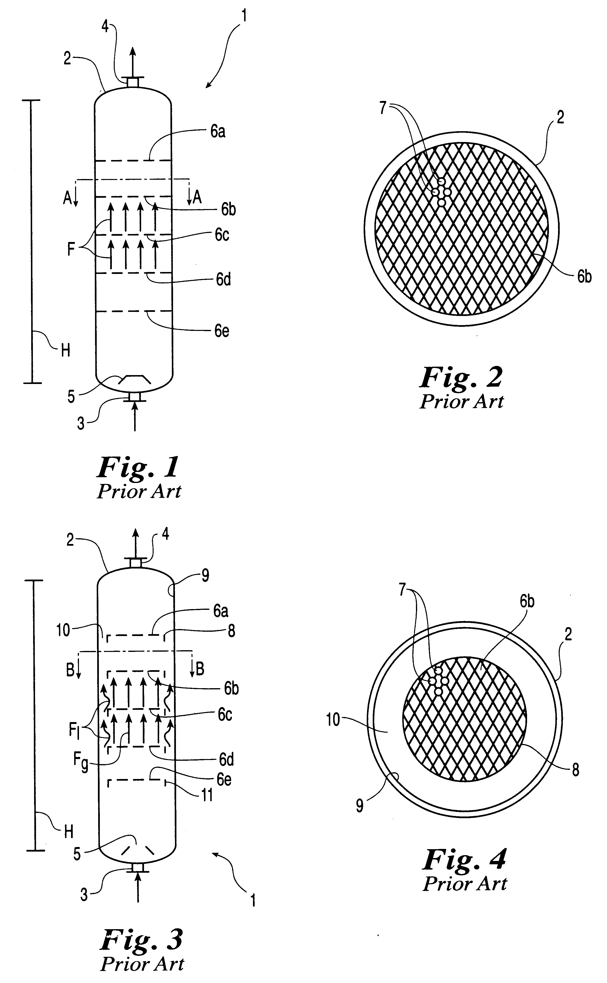
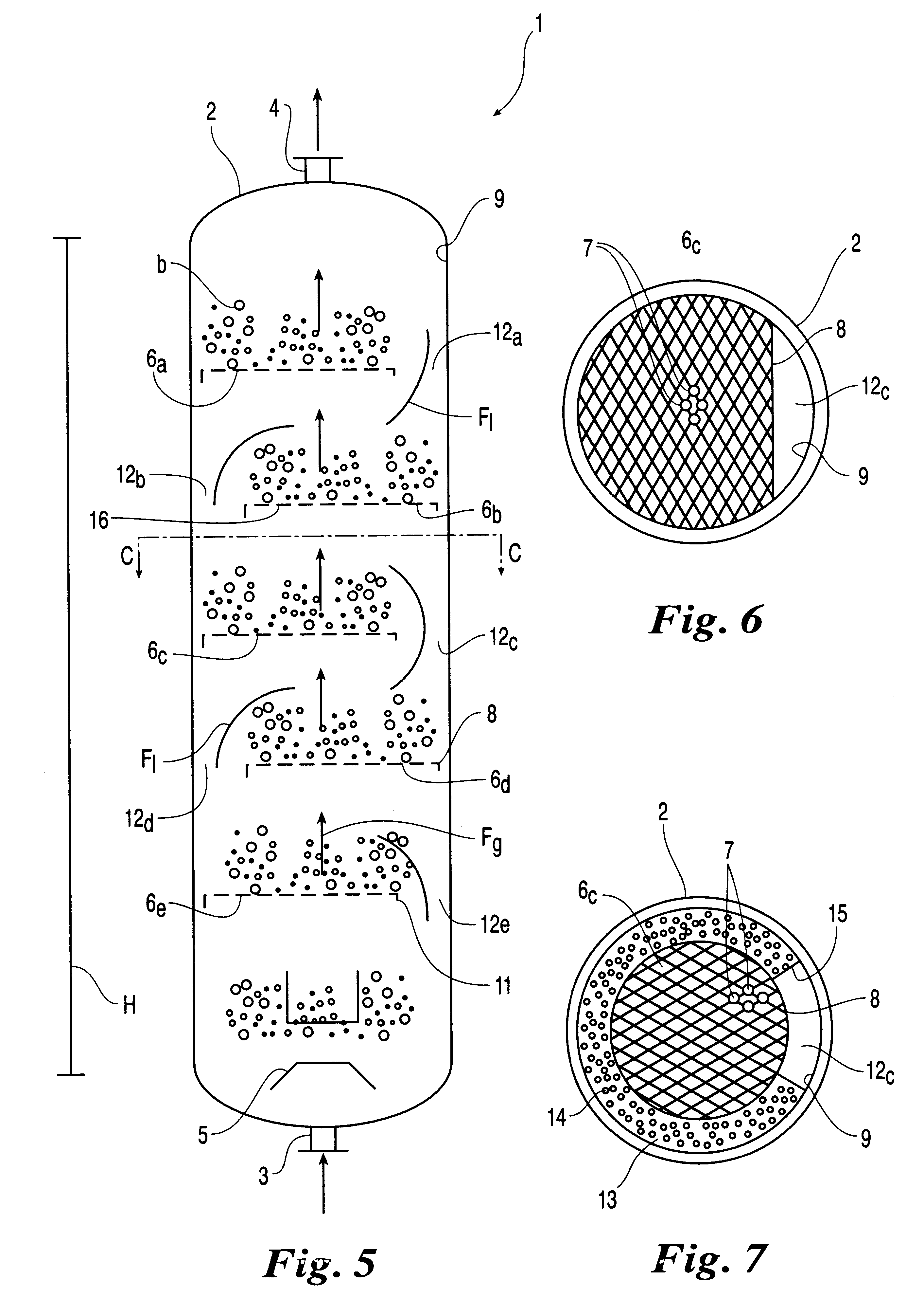
In accordance with the method in accordance with the present invention the reactor 1 of FIG. 1 is modernized by forming in at least two adjacent perforated plates 6a-6e respective openings 12a-12e for liquid flow mutually offset so as to provide a preferential flow path of the liquid phase substantially in a zigzag pattern shown in FIG. 5 by the arrow Fl.

With reference to FIG. 6 each of the openings (12a-12e) for liquid flow is preferably formed by means of removal of a peripheral portion of the plate between the internal wall 9 of the shell and the perimetric edge 8 of the plate.

second embodiment

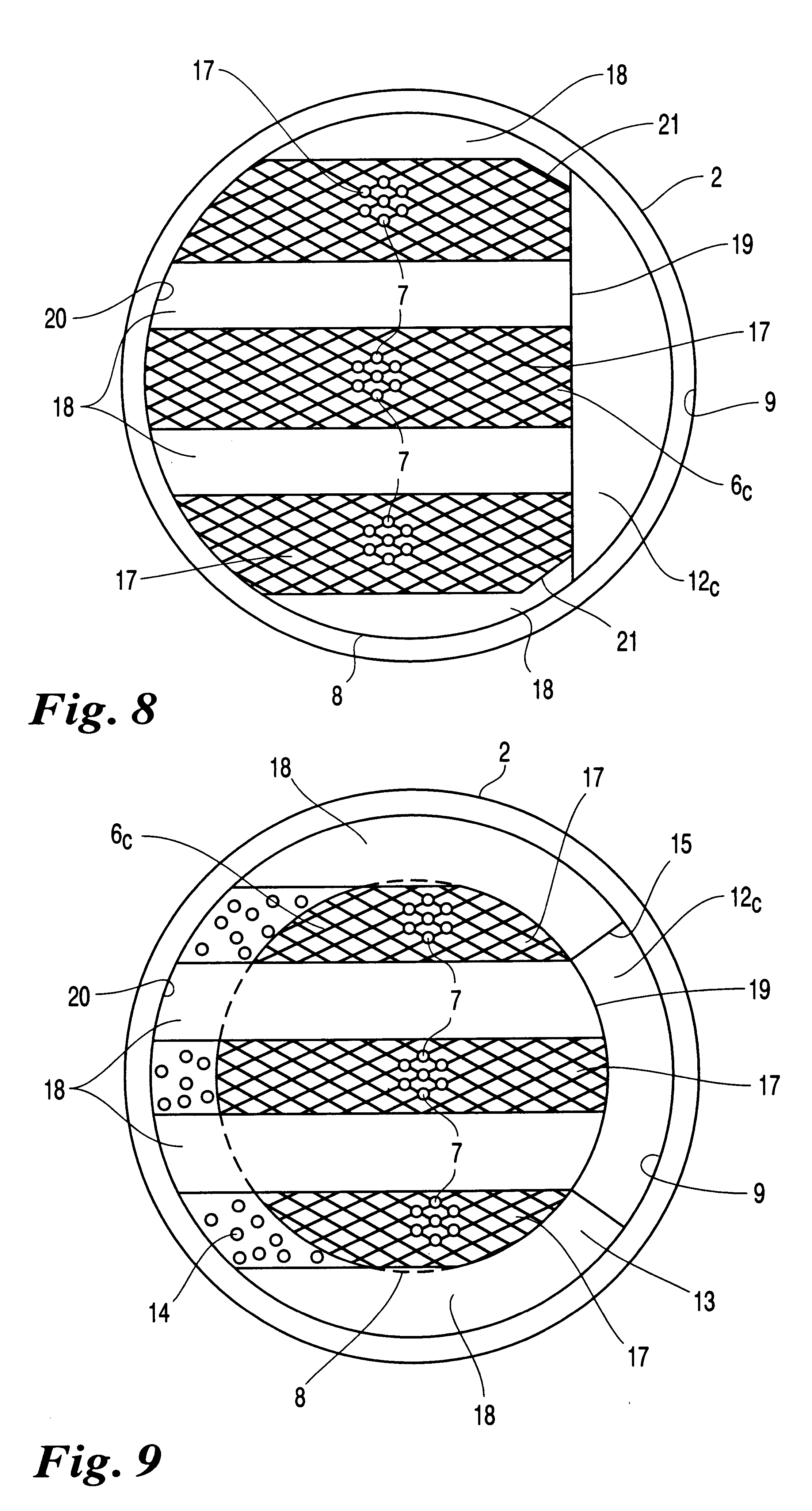
In accordance with the method in accordance with the present invention the reactor 1 of FIG. 3 is modernized by means of a step in which at least two adjacent annular apertures 10 are partially obstructed by baffles 13 defining respective openings 12a-12e for liquid flow mutually offset so as to provide a preferential zigzag flow path as described above.

This embodiment is particularly suitable with annular apertures 10 having a sufficient width so that the portion of the aperture 10 not obstructed by the baffle 13 will define an opening 12a-12e for liquid flow.

In this case, for sufficient width it is intended a width of the apertures 10 of at least 4 cm.

As shown in FIG. 7 the baffles 13 preferably have a plurality of holes all indicated by 14, which increase the passing surface of the gaseous phase in correspondence of the adjacent plates 6a-6e.

The baffles 13 are removably supported in the shell 2 in a conventional manner known in itself between the perforated plates 6a-6e and the s...

third embodiment

When the width of the apertures 10 is less than 4 cm, it is preferable to implement the method in accordance with the present invention, which calls for in-situ modernization of the reactor of FIG. 3 by means of a first step wherein the annular apertures 10 defined in correspondence of at least two adjacent plates 6a-6e are obstructed by means of baffles 13, and a second step wherein in said adjacent plates 6a-6e respective mutually offset openings 12a-12e for liquid flow are formed, so as to provide a zigzag preferential flow path for the liquid phase in said shell.

Thanks to the modernization method in accordance with the present invention it is possible to obtain at low investment cost an increase in the conversion yield and production capacity of the modernized reactor while reducing energy consumption of urea plants.

Advantageously both the perimetric edge 8 of the plates 6a-6e of FIGS. 6 and 7 and the perimetric edge 15 of the baffles 13 of FIG. 7 are provided with a collar 11 o...


PUM

PropertyMeasurementUnit
temperatureaaaaaaaaaa
pressureaaaaaaaaaa
sizeaaaaaaaaaa

Abstract

A reactor for two-phase reaction, in particular for urea synthesis at high pressure and temperature of the type wherein a co-current flow of a gaseous phase and a liquid phase takes place, comprises a substantially cylindrical vertical external shell (2) in which is supported a plurality of superimposed horizontal perforated plates (6a-6e) in mutually spaced relationship and at least one opening (12a-12e) for liquid flow being defined in correspondence of each of the perforated plates. Advantageously the openings (12a-12e) for liquid flow are mutually offset so as to obtain a substantially zigzag preferential flow path for the liquid phase in the reactor.

Description

FIELD OF APPLICATIONIn a general aspect, the present invention relates to a reactor for two-phase reactions, in particular for urea synthesis at high pressure and temperature of the type comprising:a substantially cylindrical vertical external shell,a plurality of superimposed perforated plates extending horizontally and in mutually spaced relationship in said shell, andat least one opening for liquid flow defined in correspondence of each of said perforated plates.The present invention also relates to in-situ modernization of reactors for two-phase reactions, in particular for urea synthesis at high pressure and temperature.In the description given below and in the following claims, the term: "in-situ" modernization, is understood to mean the on-site modification of a pre-existing reactor in order to improve its performance and obtain e.g. greater production capacity and / or greater conversion yield and / or reduction in energy consumption.In the terminology of the field this type of ...

Claims


Application Information

Patent Timeline
Patent Type & Authority Patents(United States)
IPC IPC(8): B01J3/04B01J19/00B01D3/22B01D3/14B01J10/00C07C273/00C07C273/04
CPCB01D3/22B01J3/04B01J10/002B01J19/006C07C273/04B01J2219/00777B01J2219/185B01J2219/1943B01J2219/00024Y02P20/582Y02P20/141
Inventor ZARDI, FEDERICOSILVA, PAOLO
Owner UREA CASALE SA
Why Eureka
Try Eureka