Wastewater treatment plant

a technology for treatment plants and wastewater, which is applied in the direction of sedimentation settling tanks, liquid displacement, separation processes, etc., can solve the problems of low separation yield efficiency of the current plant on the market, and achieve the effect of easy production and optimal performan

Active Publication Date: 2014-12-18
WAMGRP
View PDF7 Cites 0 Cited by
  • Summary
  • Abstract
  • Description
  • Claims
  • Application Information

AI Technical Summary

Benefits of technology

[0004]The object of the present invention is, therefore, to produce a plant for separating at least one inorganic material from a fluid containing, furthermore, a certain quantity of suspended organic material that is easy to produce, while ensuring optimal performance in terms of general yields.
[0005]In other words, by means of the plant forming the object of the invention, adequate solid / liquid separation has been obtained, reducing both the size and the structural complexity of the plant, thus reaching a high degree of efficiency.

Problems solved by technology

Plants currently present on the market are not very efficient with regard to the separation yield of the inorganic material, for example sand, from the fluid part.

Method used


Image

  • Wastewater treatment plant
  • Wastewater treatment plant

Examples


Embodiment Construction

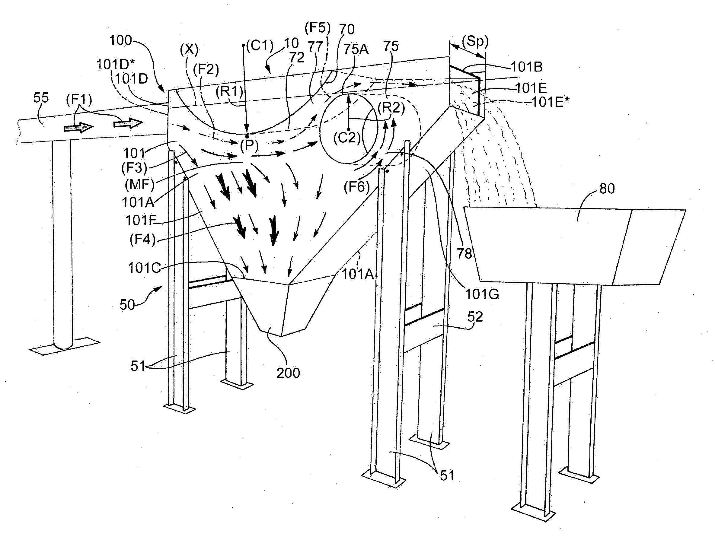
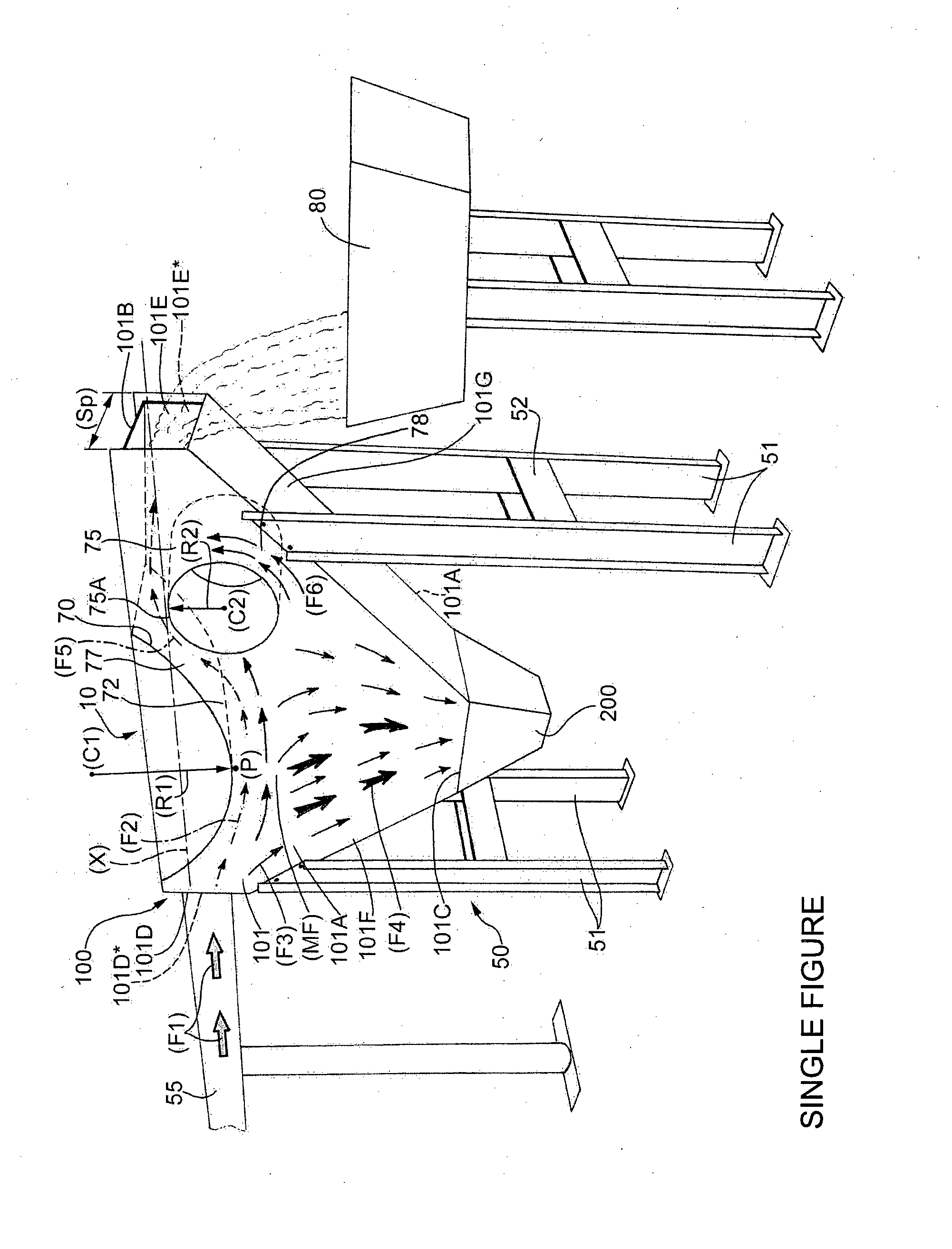
[0013]As will be seen in more detail hereunder, the plant 10 comprises separating equipment 100 for separating the solid particles from the fluid part.

[0014]The whole plant 10 is supported by a supporting structure 50 comprising a series of pillars 51 held together by a plurality of cross members 52. It is obvious that, in place of the supporting structure 50 shown in the FIGURE, it is possible to adopt any load-bearing structure suitable for the purpose.

[0015]The separating equipment 100 is supplied by a pipe 55 with wastewater that flows according to a direction and a sense indicated by an arrow (F1) substantially aligned with a horizontal axis (X). Normally, the wastewater treated in this type of plant is a mixture comprising a mass of water in which particles of organic waste, such as hydrocarbons, and inorganic substances, such as sand, are dispersed.

[0016]Analysing the separating equipment 100 in greater detail, it can be noted that it comprises a central tank 101 to which the...


PUM

PropertyMeasurementUnit
massaaaaaaaaaa
radiusaaaaaaaaaa
sizeaaaaaaaaaa

Abstract

A wastewater treatment plant. The plant comprises separating equipment for separating the solid particles from the liquid part. The separating equipment comprises, in turn, an inlet opening and an outlet opening, which are substantially arranged in line along a common directrix. In the fluid mass, there is present at least one fluid-dynamic profile, which is suited to help the detachment of the solid particles from the liquid part. The plant is characterised in that the separating equipment comprises, furthermore, a second fluid-dynamic profile. The two fluid-dynamic profiles define between one another a first preferential flow channel of the liquid mass.

Description

TECHNICAL FIELD[0001]The present invention relates to a wastewater treatment plant. In this plant the organic materials that rise to the surface of the liquid mass are separated from the solid inorganic materials that decant on the bottom.[0002]In particular, the present invention can be advantageously, but not exclusively, applied in plants in which a liquid mass must be purified from the sand contained therein.BACKGROUND ART[0003]Plants currently present on the market are not very efficient with regard to the separation yield of the inorganic material, for example sand, from the fluid part.DISCLOSURE OF INVENTION[0004]The object of the present invention is, therefore, to produce a plant for separating at least one inorganic material from a fluid containing, furthermore, a certain quantity of suspended organic material that is easy to produce, while ensuring optimal performance in terms of general yields.[0005]In other words, by means of the plant forming the object of the inventio...

Claims


Application Information

Patent Timeline
Patent Type & Authority Applications(United States)
IPC IPC(8): B01D21/26
CPCC02F2301/02B01D21/26B01D21/0042C02F2001/007C02F2301/028C02F2303/24B01D21/0075B01D21/0087B01D21/02C02F1/52E03F5/14B01D21/0063
Inventor MARCHESINI, VAINER
Owner WAMGRP
Why Eureka
Try Eureka