Blockable piston-cylinder unit

Inactive Publication Date: 2001-01-30
STABILUS
View PDF10 Cites 22 Cited by
  • Summary
  • Abstract
  • Description
  • Claims
  • Application Information

AI Technical Summary

Benefits of technology

According to the invention, the foregoing objects are achieved by the provision of a throttle arrangement between two individual closing valves, which throttle arrangement produces a reduction in pressure between the valve outflow side of the first closing valve towards the valve inflow side of the following, second closing valve. The effect of the throttle arrangement decreases with the increasing degree of opening of the first closing valve, and to the same extent the pressurization of the second closing valve increases on the valve inflow side. The purpose is to produce a controlled coordination of the dynamic pressure between the individual valves, so that there will occur no pressure peaks which might lead to drastic motions of the valve, which motions in turn will be unpleasantly audible as noise.
In the case of a piston-rod motion in which the working space 23 decreases, from a specific stroke position onward the retaining element 93 moves into the stepped inner wall of the stop sleeve 113 with a velocity that is almost constant. The medium contained in working space 23--as already explained, generally a hydraulic fluid--can flow through the opened valves 27, 47 of the piston. As soon as the front surface 125 of the retaining element 93 abuts against the shoulder surface 123, a damping force builds up because of the damping orifice 127, reducing the velocity of the piston. The front surface 125 and the shoulder surface 123 then constitute an at least dynamically effective seal. The damping effect is thus purposely determined exclusively by the cross-section of the damping orifice 127.

Problems solved by technology

One of the problems of a unit capable of being blocked in infinite steps is the noticeable switching noise.
This type of noise did not occur in the case of earlier, defined blocking position types of piston-cylinder units, and is detrimental to comfort.
In so doing, one would also affect the retaining force of the piston-cylinder unit via the prestressing of the valve ring, which in some cases could be undesirable, however.
Furthermore, the sealing lip that is located beyond the groove is lifted in case of a sliding motion of the valve ring, and thereby prestresses the entire valve ring.

Method used


Image

  • Blockable piston-cylinder unit
  • Blockable piston-cylinder unit
  • Blockable piston-cylinder unit

Examples


Embodiment Construction

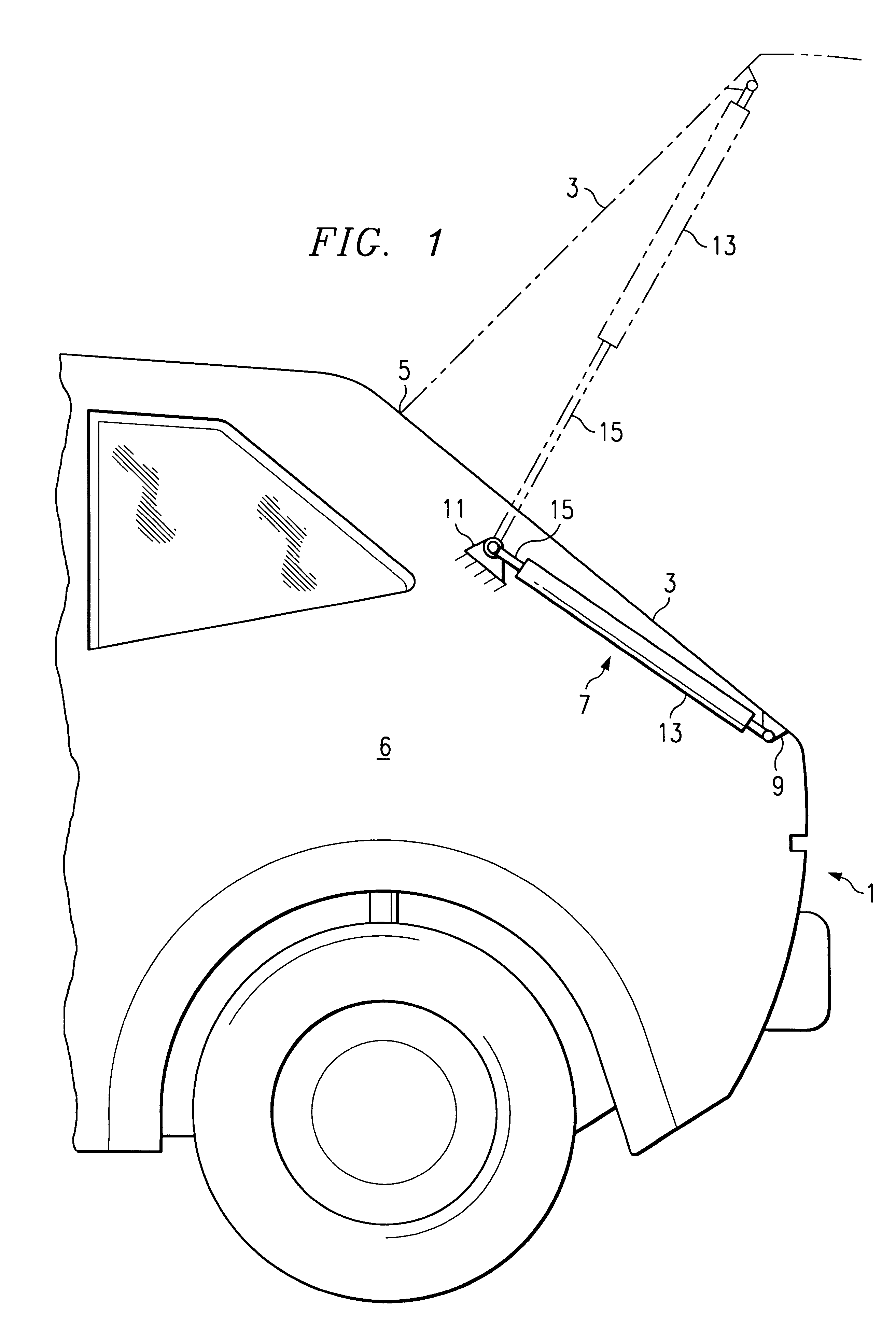
FIG. 1 shows in diagrammatic fashion a motor vehicle 1 with a vehicle trunk lid 3 which is arranged in movable fashion around a pivot axis 5 which is aligned perpendicularly to the longitudinal axis of the vehicle. In order to facilitate the opening movement, a piston-cylinder unit 7 is articulated in movable fashion via connecting elements 9, 11 between the vehicle body 6 and the vehicle trunk lid 3. The piston-cylinder unit comprises a cylinder 13 and a piston rod 15 which is axially movable therein. One of the components 13, 15 engages with the vehicle body (at 11) and the other with the vehicle trunk lid (at 9), so that a motion of the vehicle trunk lid proceeds in synchronous fashion with the inward or outward motion of the piston rod 15. The use of the piston-cylinder unit 7 is not limited to vehicle trunk lids but can also be transferred to other applications, such as vehicle doors.

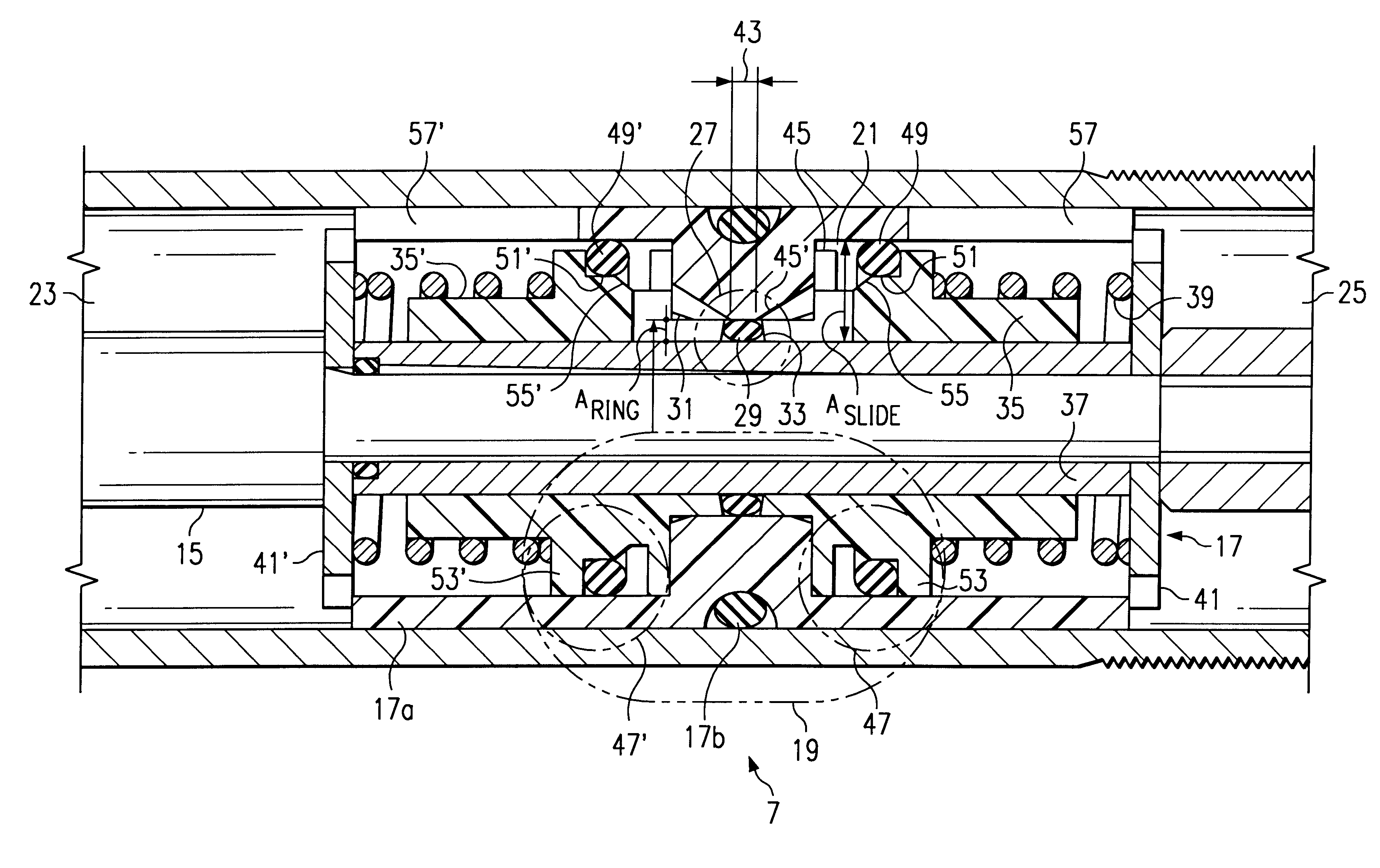
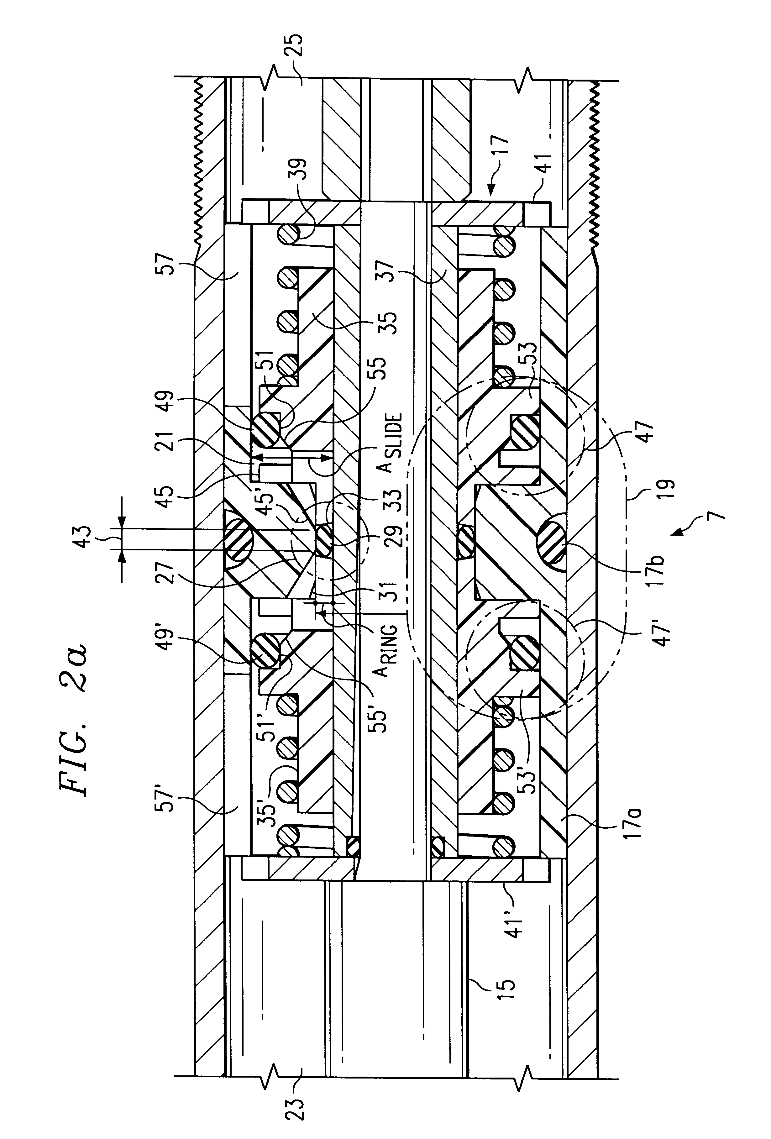
An initial example of an embodiment of the invention is shown in FIGS. 2a and 2b. The illustrat...


PUM


Abstract

A piston-cylinder unit, comprising a cylinder which is subdivided by a piston on a piston rod into two working chambers. Between the two working chambers, there is a fluid connection which can be blocked by means of a valve arrangement having at least two individual closing valves arranged in series, each with a valve inflow side and a valve outflow side. The valves open sequentially. In the flow path between the individual valves, there is a throttle arrangement which produces a pressure reduction between the valve outflow side of the first closing valve towards the valve inflow side of the following closing valve. As the opening of the first closing valve increases, the effect of the throttle arrangement decreases; to the same extent, the pressurization increases on the valve inflow side of the following closing valve. The valve arrangement features two flow-through directions and is made so that each can be blocked.

Description

1. Field of the InventionThe present invention concerns a bidirectionally blockable piston-cylinder unit which includes a throttle arrangement to control fluid flow therethrough so as to minimize noise upon switching between opened and closed positions.2. The Prior ArtA positional piston-cylinder unit to lock movable objects in relative positions to each other is known from DE 4,326,968 A1. Such positional locks are used, among others, in the case of vehicle doors or lids, which on the one hand, should be easily manipulated, but, on the other hand, should also safely carry the respective load. One of the advantages of a piston-cylinder lock according to DE 4,326,968 A1 is that it is possible to make the retaining function independent of the stroke. Other types of units allow the retaining function to occur only within a specific opening range of the vehicle door or lid, or else only in predetermined fixed resting steps.One of the problems of a unit capable of being blocked in infini...

Claims


Application Information

Patent Timeline
IPC IPC(8): E05C17/30E05C17/00F16F9/512F16F9/34F16F9/56F16F9/50B60J5/04E05F3/04B60J5/10E05C17/48F16F9/00F16F9/52
CPCE05C17/305F16F9/3405F16F9/5126F16F9/56
Inventor MINTGEN, ROLFROTHE, WOLFGANGRENNECKE, DIRKRITTER, ANDREASGEHLEN, MARCO
Owner STABILUS
Why Eureka
Try Eureka