Motor-pump arrangement

a technology of motor housing and housing, which is applied in the direction of positive displacement liquid engines, piston pumps, braking systems, etc., can solve the problems of poor sealing of the motor housing, lack of sturdiness of the housing, and moisture entering the area of contact with the pump housing, etc., to achieve high radial force, high protection, and high strength

Inactive Publication Date: 2001-01-30
ROBERT BOSCH GMBH
View PDF5 Cites 18 Cited by
  • Summary
  • Abstract
  • Description
  • Claims
  • Application Information

AI Technical Summary

Benefits of technology

The motor-pump arrangement has the advantage over the prior art that it has high strength and that the motor housing is well protected against the invasion of liquid.
Because a preferably metal cap is press-fitted into an open end of the cup-shaped motor housing, high radial forces can be absorbed on both face ends of the housing. Moreover, the cap can be press-fitted into the motor housing and thus secured in a single mounting step.
Preferably, the cap is embodied such that at least two radially spaced-apart annular seals can be mounted, preferably in the grooves provided in the cap face. This has the advantage of achieving very high protection against invading liquid in the region of the drive shaft.
The use of shaped sealing rings for the seals has proved to be especially advantageous. A further advantageous possibility is to produce the seal by injection-molding using a sealing material. A particular advantage is also considered to be that the cap is prefabricated with the two seals and can be mounted as a unit on the motor housing.
In another advantageous feature, the cap is embodied as a spring element. In this connection, spring element means that upon an imposition, for instance by a radial force, the cap yields resiliently and in the process the cap curves somewhat. On the one hand, this attains the advantage that the cap is seated securely and tightly in the housing with a certain prestressing. On the other, very good sealing can be attained between the cap and the adjoining pump housing, because the pump housing is pressed against the curvature of the cap and secured.
In another advantageous feature, a commutator of the electric motor and the current-carrying brushes are mounted on the cap side of the motor housing. This has the advantage that contacting the brushes by means of lines that are extended through the cap and the pump housing to a downstream control unit is simply unnecessary.

Problems solved by technology

One disadvantage of this motor-pump unit is considered to be that the sealing of the motor housing is not optimal.
Especially if the plastic cap is not manufactured to precise dimensions, it is possible that moisture may enter in the area of contact with the pump housing.
Moreover, because of the plastic cap used, the motor housing lacks sturdiness, and the absorption of radial forces in the region of the housing opposite the cup bottom is restricted.

Method used


Image

  • Motor-pump arrangement
  • Motor-pump arrangement

Examples


Embodiment Construction

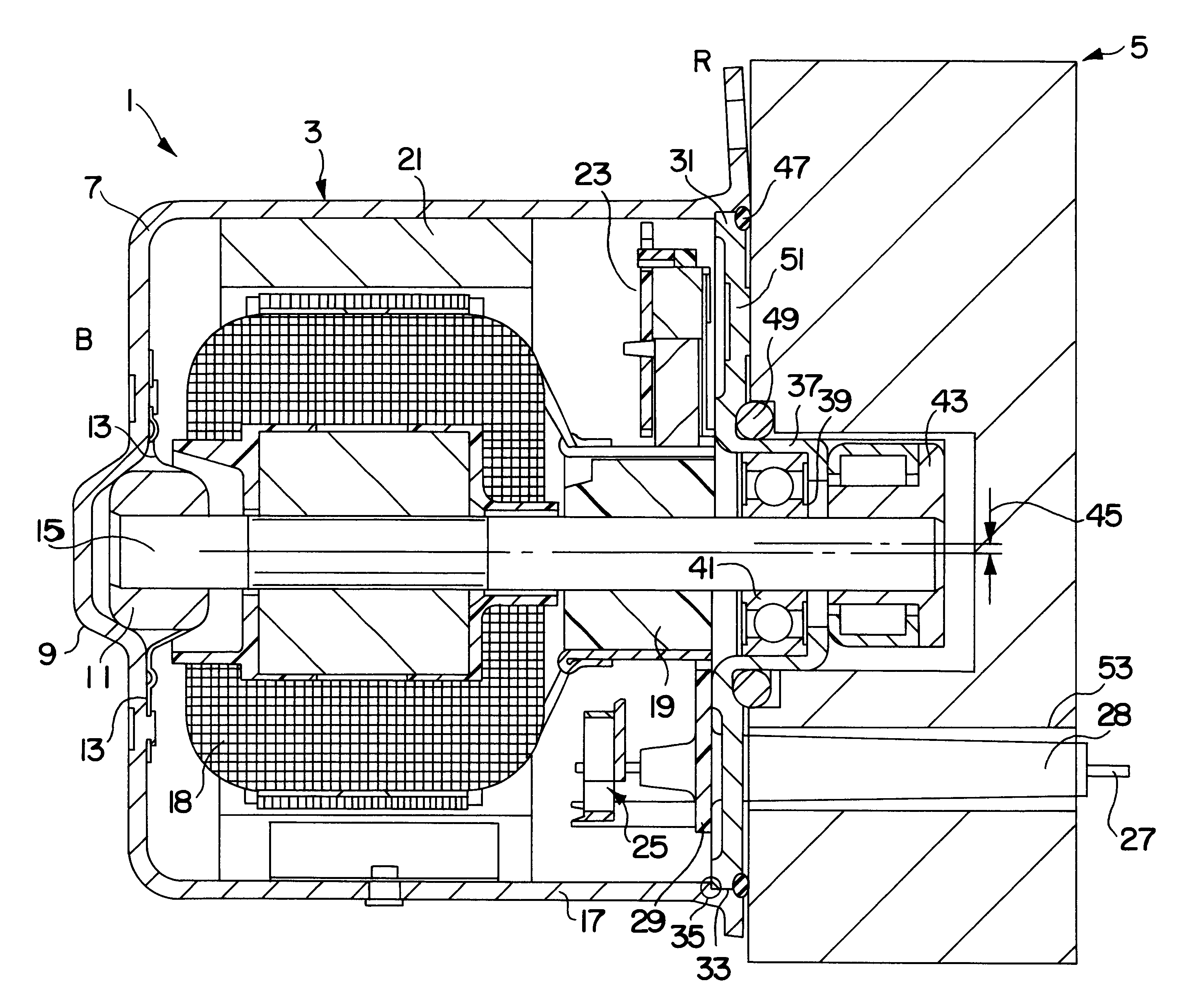
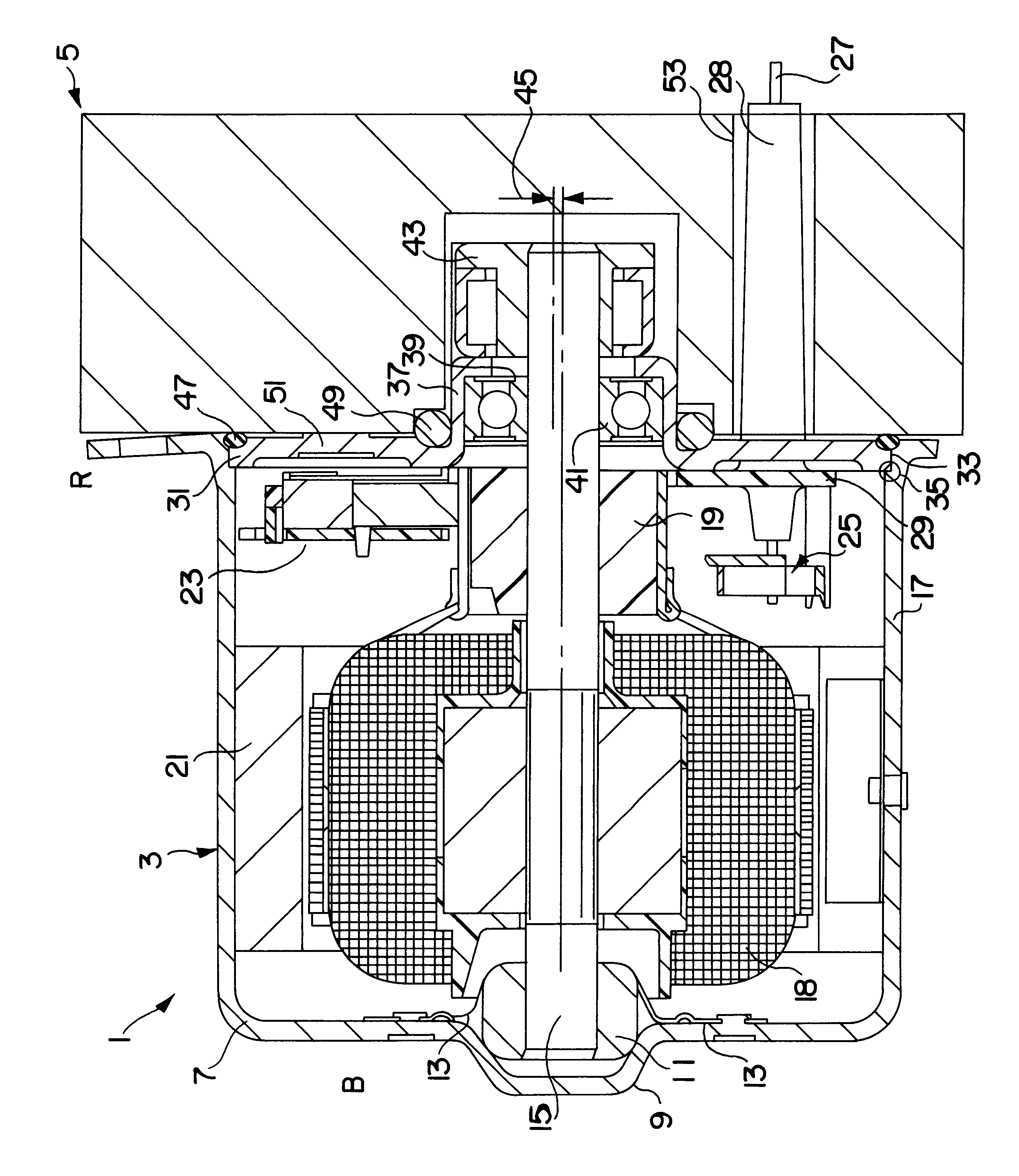
In the drawing, a motor-pump arrangement 1 can be seen, which includes an electric motor 3 and a merely schematically shown pump unit 5. Such a structural unit is employed for instance as a high-pressure pump for hydraulic brake fluid, preferentially in ABS systems.

The electric motor 3 has a cup-shaped motor housing 7, on the bottom region B of which a bulge 9 is provided. This outward-oriented bulge 9 has a radial width that in at least one region is equivalent to the diameter of a bearing 11 to be received. Along with the supporting of the bearing in the bulge 9, additional straps 13 are provided, which assure both a radial and an axial fixation of the bearing.

A shaft 15 is supported in the bearing 11; it extends through the motor housing 7 substantially parallel to a cylinder wall 17 of the housing and protrudes by a certain extent past an edge R of the housing.

Windings of a rotor 18 are mounted in a known manner, fixed against relative rotation, on the drive shaft, as is a commu...


PUM


Abstract

The invention relates to a motor-pump arrangement, having a cup-shaped motor housing for receiving an electric motor, and a pump housing that can be mounted on the motor housing. The pump housing can be mounted on the face end (R) of the motor housing opposite the cup bottom, and that a cap is provided, which can be pressed into the motor housing on the open face end and seals off this housing, the cap has a central bore for a drive shaft and at least one further opening, near the edge, for a through-plated hole.

Description

PRIOR ARTThe invention relates to a motor-pump arrangement, having a cup-shaped motor housing for receiving an electric motor, and a pump housing that can be mounted on the motor housing.From European Patent Disclosure EP 0 645 875 B1, a motor-pump unit is disclosed that has both a cup-shaped motor housing and a pump housing mounted on the motor housing. A bearing neck is embodied on the cup bottom of the motor housing and on one side receives at least one bearing, intended for supporting a drive shaft, and an eccentric element that serves to drive pump parts. In other words, the pump housing is seated on the cup bottom end face, and the bearing neck protrudes into the pump housing.To prevent liquid, such as moisture, from penetrating to the interior of the motor housing, the pump housing rests sealingly on the cup bottom face of the motor housing. The open face end of the motor housing opposite the cup bottom is sealed off by a plastic cap placed on it, the edge of the cap abutting...

Claims


Application Information

Patent Timeline
Patent Type & Authority Patents(United States)
IPC IPC(8): B60T8/40F04B17/03H02K5/10H02K7/14H02K5/22H02K5/14
CPCB60T8/4022F04B17/03H02K5/10H02K5/225H02K7/14H02K5/148
Inventor HUBER, MARTINBRAUN, WILHELM
Owner ROBERT BOSCH GMBH
Why Eureka
Try Eureka