

Emergency stop switch mechanism for a robot and teaching operation panel provided with the mechanism
a technology of emergency stop switch and robot, which is applied in contact mechanisms, electric programme control, instruments, etc., can solve the problems of difficult application of external force, affecting the operation not always being able to reflect on the action taken, so as to improve the operability of the teaching operation panel, improve the effect of construction efficiency and secure the operator's safety
- Summary
- Abstract
- Description
- Claims
- Application Information
AI Technical Summary
Benefits of technology
Problems solved by technology
Method used
Image

Examples
first embodiment
( FIGS. 8a to 8c)
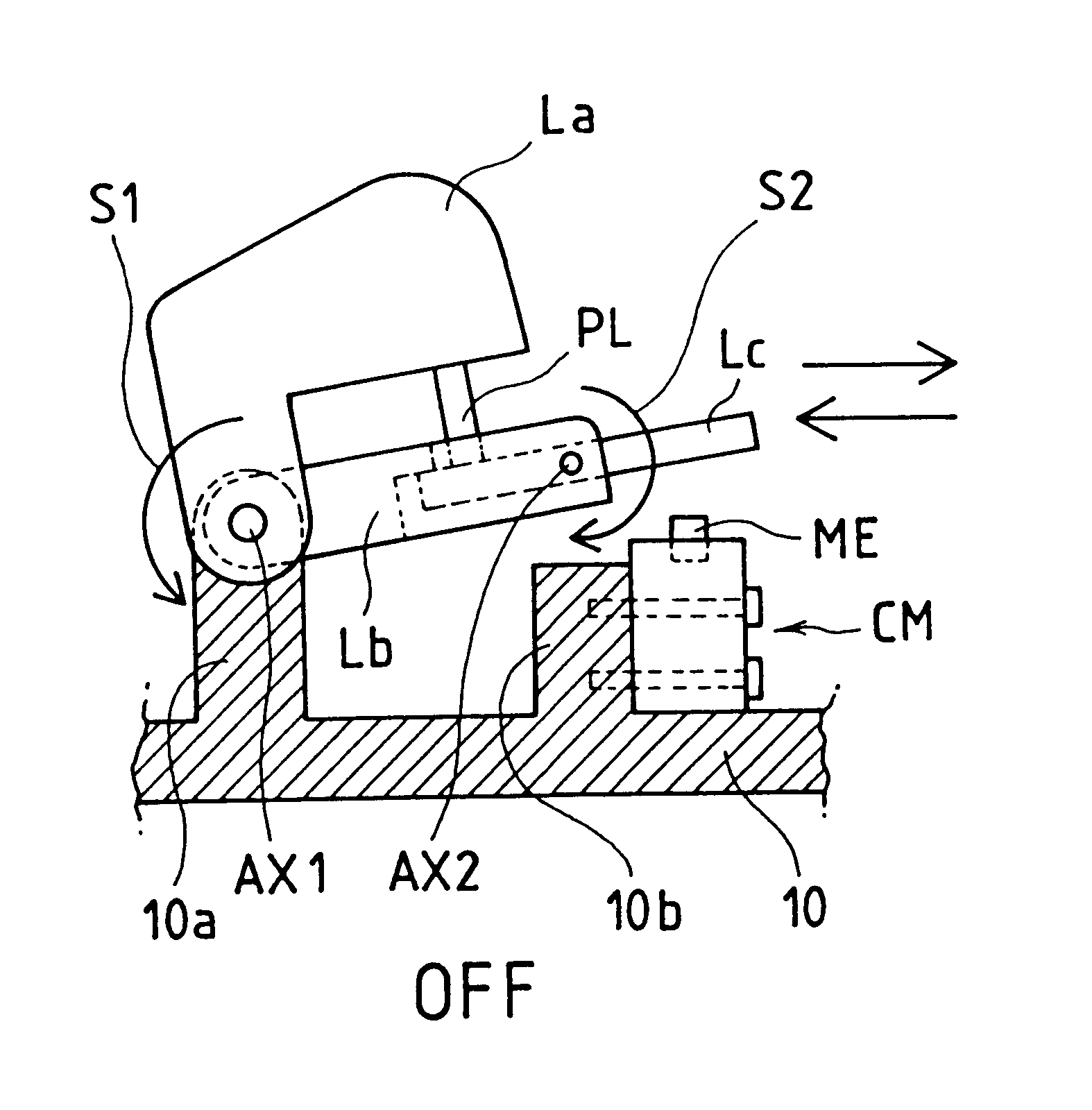
A main lever La, which is provided as an external operation force applicator for a deadman switch mechanism so as to be exposed on the operation surface of a teaching operation panel, is pivotally supported by an axis AX1, together with a first ancillary lever Lb, with an elastic biasing force S1 indicated by the arrow mark. The axis AX1 is provided on columns 10a (for example, two columns) extending from a teaching operation panel body 10 in the form of a publicly known spring biasing pivot mechanism.
In the vicinity of the tip end of the first ancillary lever Lb, a second ancillary lever Lc is pivotally supported by another axis AX2 with an elastic biasing force S2 indicated by the arrow mark. The main lever La is provided with a plunger PL in such a manner that a pressing force can be applied to the second ancillary lever Lc with a left point in FIGS. 8a to 8c with respect to the axis AX2 (opposite to a movable contact element ME) being a point of application.
The ...
second embodiment
( FIGS. 9a to 9c)
A main lever La, which is provided as an external operation force applicator for a deadman switch mechanism so as to be exposed on the operation surface of a teaching operation panel, is pivotally supported by an axis AX1, together with a first ancillary lever Lb, with an elastic biasing force S1 indicated by the arrow mark. The axis AX1 is provided on columns 10a (for example, two columns) extending from a teaching operation panel body 10 in the form of a publicly known spring biasing pivot mechanism.
In the vicinity of the tip end of the first ancillary lever Lb, a second ancillary lever Lc is pivotally supported by another axis AX2 with an elastic biasing force S2 indicated by the arrow mark. The main lever La is provided with a plunger PL in such a manner that a pressing force can be applied to the first ancillary lever Lc with a point near the axis AX2 being a point of application.
The elastic biasing force S1 should preferably be designed to have a magnitude of ...
third embodiment
( FIGS. 10a to 10c)
A main lever La, which is provided as an external operation force applicator for a deadman switch mechanism so as to be exposed on the operation surface of a teaching operation panel, is pivotally supported by an axis AX1, together with a first ancillary lever Lb, with an elastic biasing force S1 indicated by the arrow mark. The axis AX1 is provided on a column 10a extending from a teaching operation panel body 10 in the form of a publicly known spring biasing pivot mechanism.
In the vicinity of the tip end of the first ancillary lever Lb, a second ancillary lever Lb is pivotally supported by another axis AX2 with an elastic biasing force S2 indicated by the arrow mark. Also, in the vicinity of the other end of the second ancillary lever Lc, one end of a link LK is pivotally supported by an axis AX3. In the vicinity of the tip end of the main lever La, the other end of the link LK is pivotally supported by an axis AX4.
The elastic biasing force S1 should preferably ...
PUM
 Abstract
Description
Claims
Application Information