Plasma generating apparatus

a technology of generating apparatus and plasma, which is applied in the direction of plasma technique, coating, electric discharge lamps, etc., can solve the problems of limited choice of working gases, relatively narrow limits of gas pressure, and relatively low attainable average energy release in the gas medium

Inactive Publication Date: 2001-01-30
DAEWON PAPTIN FOAM
View PDF1 Cites 18 Cited by
  • Summary
  • Abstract
  • Description
  • Claims
  • Application Information

AI Technical Summary

Problems solved by technology

One of the main disadvantages of this method consists in a limited choosing of a working gases and relatively narrow limits of gas pressure at which gas discharge ex

Method used


Image

  • Plasma generating apparatus
  • Plasma generating apparatus
  • Plasma generating apparatus

Examples


Embodiment Construction

Reference will now be made in detail to the preferred embodiments of the present invention, examples of which are illustrated in the accompanying drawings.

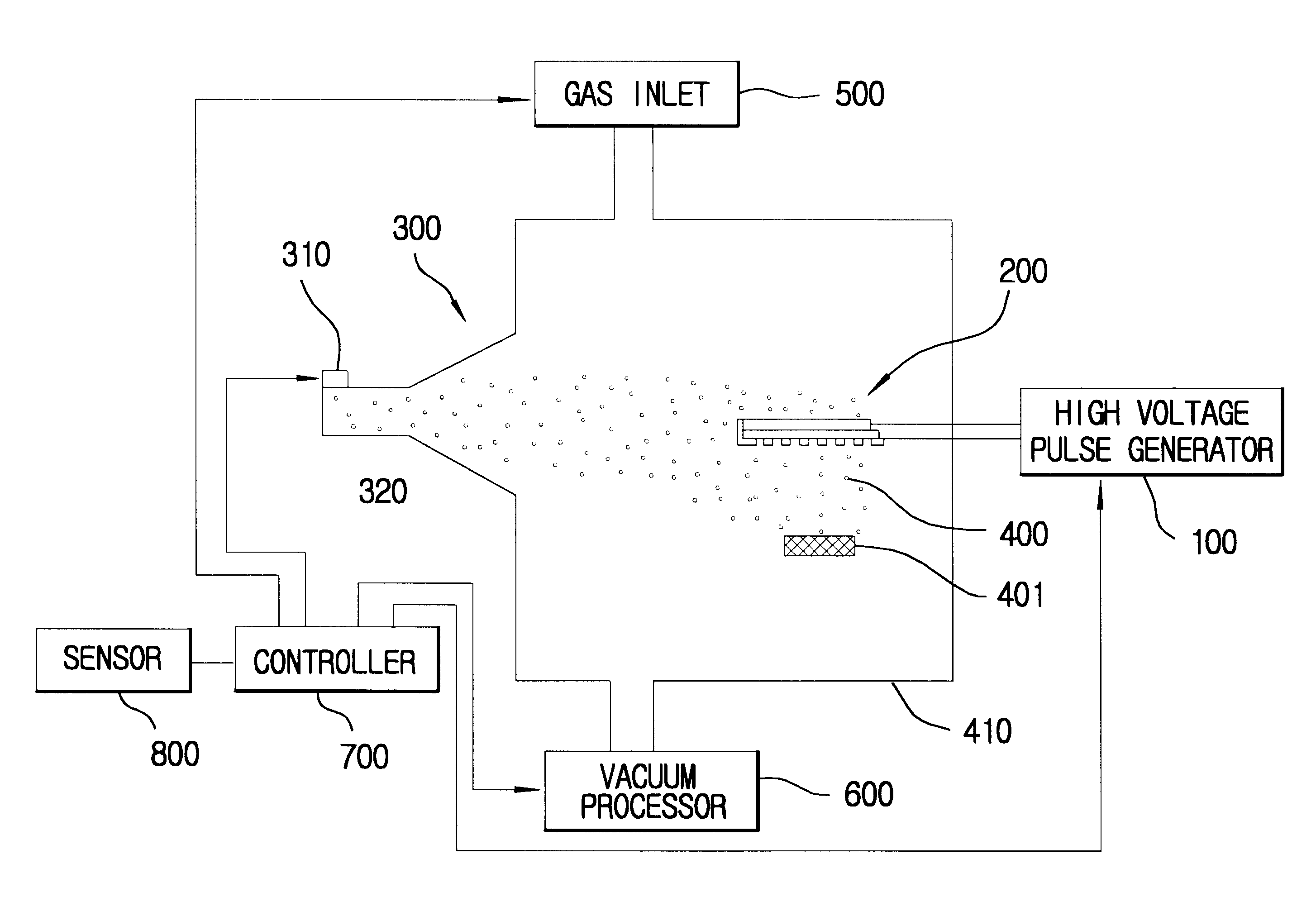
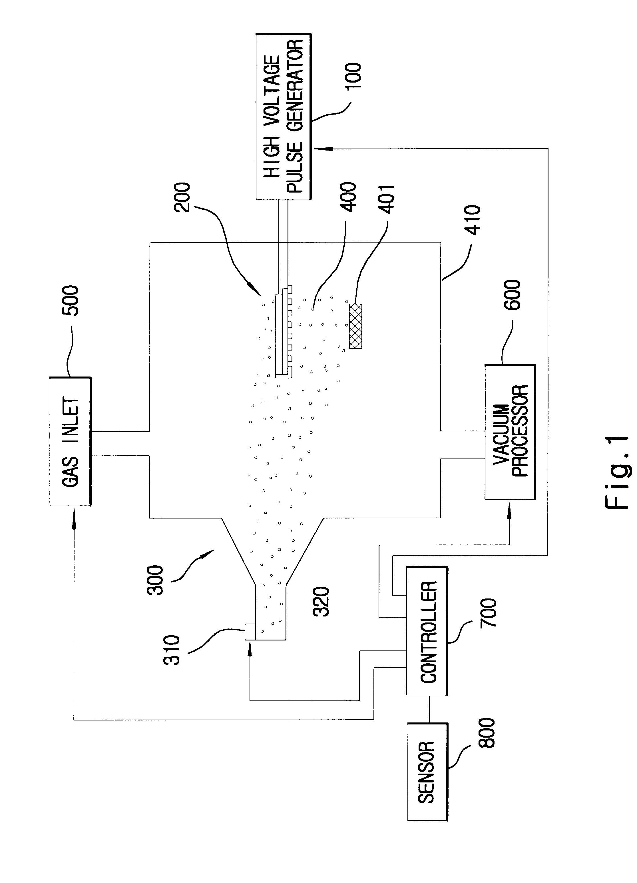
Referring to FIG. 1, a plasma generating apparatus according to the present invention includes a high voltage pulse generator 100 for generating a high voltage pulse, a plasma generator 200 on which slipping surface discharge is excited generating plasma, microwave generator 300 for generating a microwave radiation, a chamber 410 in which the plasma collects, a gas inlet 500 through which a gas flows into the chamber to generate the plasma, a vacuum processor 600 for reducing the atmospheric pressure in chamber 410, a sensor 800 for detecting the atmospheric pressure state and gas flow state in chamber 410, and a controller 700 for controlling the operations of high voltage pulse generator 100, high frequency generator 300, gas inlet 500 and vacuum processor 600.

High voltage pulse generator 100 generates a high voltage pulse with ...


PUM

PropertyMeasurementUnit
Frequencyaaaaaaaaaa
Pressureaaaaaaaaaa
Lengthaaaaaaaaaa

Abstract

A plasma generating apparatus is provided which uses slipping surface discharge and microwave to generate a large quantity of plasma in a different gases or gaseous mixtures (including electro-negative gases) in a wide range of gas pressure (from a deep vacuum up to atmospheric pressure). The plasma generating apparatus includes high voltage pulse means for generating a high voltage pulse, plasma generating means based on the slipping surface discharge which excites as the high voltage pulse generated by high voltage pulse generating means, is supplied, microwave generating means for generating a microwave radiation for producing plasma, a chamber in which the plasma generating means are placed, and the plasma collects, the chamber receiving the microwave radiation from the microwave generating means, and a gas inlet through which a specific gas flows into the chamber, to generate a large quantity of plasma according to the plasma generating means and microwave generating means.

Description

1. Field of the InventionThe present invention relates to a plasma generating apparatus, and in particular, to a plasma generating apparatus for generating a large quantity of plasma using slipping surface discharge (SSD) and microwave discharge.2. Discussion of Related ArtMicrowave gas-discharge plasma source are of considerable current use in a modern technique and technology for a PCVD thin films deposition, etching of a metallic and dielectric samples, activation of dielectric samples, etc. The advantages of these sources consist in a relatively pure conditions of a plasma generation and maintenance as well as in a high efficiency of microwave source energy release in a plasma formation and as a consequence in the gas medium, etc. One of the main disadvantages of this method consists in a limited choosing of a working gases and relatively narrow limits of gas pressure at which gas discharge excitation is possible."Slipping" discharge along the metal-dielectric surfaces also fall...

Claims


Application Information

Patent Timeline
IPC IPC(8): H01J37/32H05H1/24H05H1/00
CPCH01J37/32192H05H1/24H05H1/46H05H1/461H05H1/4645H05H1/00
Inventor HUR, BANG UKBARK, YOO BYUNGGRITSININ, SERGEIKOSSYI, IGORSERGEITCHEV, K. F.
Owner DAEWON PAPTIN FOAM
Why Eureka
Try Eureka