Analog signal detecting circuit, and AC side current detector of semiconductor power conversion device

a technology of analog signal detection and ac side current, which is applied in the direction of power supply testing, instruments, measurement using digital techniques, etc., can solve the problems of high performance load control, inability to provide an analog signal detecting circuit with high reliability and long lifetime under a bad environment, and inability to provide a high-reliability analog signal detecting circuit with long lifetim

Inactive Publication Date: 2001-01-30
MITSUBISHI ELECTRIC CORP
View PDF9 Cites 69 Cited by
  • Summary
  • Abstract
  • Description
  • Claims
  • Application Information

AI Technical Summary

Problems solved by technology

However, since the photocoupler 10 is used for electrical insulation of the digital signal, it is impossible to provide an analog signal detecting circuit having high reliability and long lifetime under a bad environment.
Besides, since the input analog signal is temporarily converted into the digital signal having a frequency uniquely corresponding to the analog signal level by using the V/F converter 8, th

Method used


Image

  • Analog signal detecting circuit, and AC side current detector of semiconductor power conversion device
  • Analog signal detecting circuit, and AC side current detector of semiconductor power conversion device
  • Analog signal detecting circuit, and AC side current detector of semiconductor power conversion device

Examples


embodiment 1

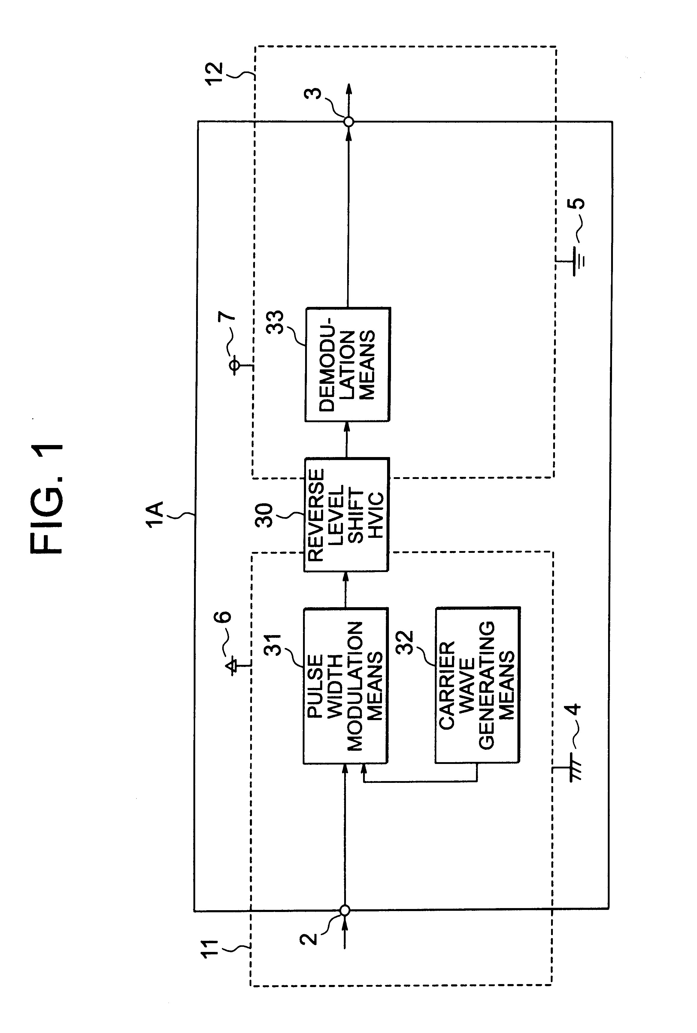
An analog signal detecting circuit of embodiment 1 of this invention will be described with reference to the drawings. FIG. 1 is a view showing the structure of the analog signal detecting circuit of the embodiment 1 of this invention. Note that the same reference characters in the respective drawings designate the same or like portions.

In FIG. 1 reference characters 1A designates an analog signal detecting circuit; 30, a reverse level shift HVIC; 31, pulse width modulation means; 32, carrier wave generating means; and 33, demodulation means. Note that the other components are the same as FIG. 6.

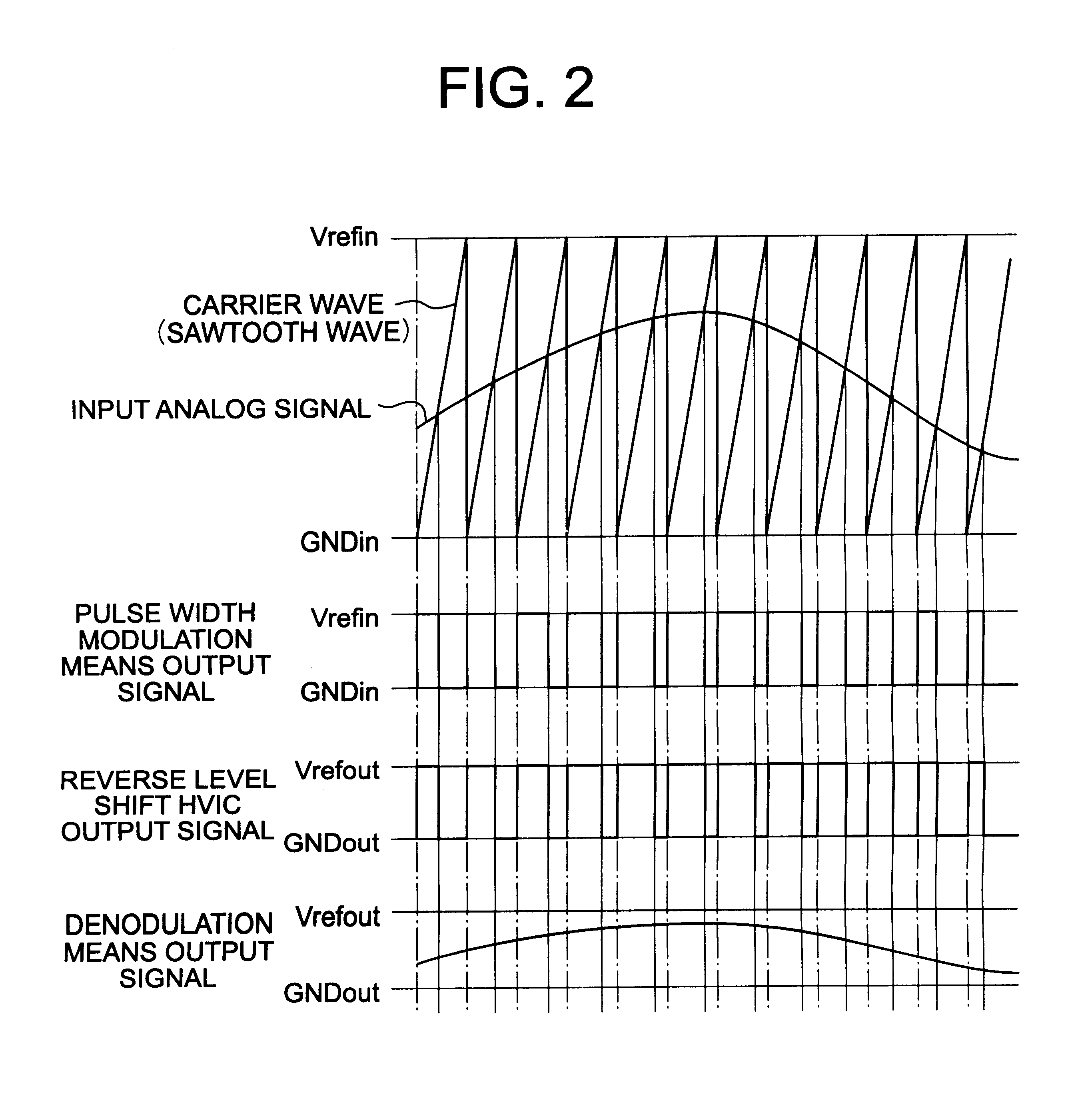
Next, the operation of the analog signal detecting circuit of this embodiment 1 will be described with reference to the drawings. FIG. 2 is a timing chart showing the operation of the analog signal detecting circuit of the embodiment 1 of this invention.

The side of a signal input terminal 2 of the analog signal detecting circuit 1A is operated with a power supply system 11 of a power supply ...

embodiment 2

An analog signal detecting circuit of embodiment 2 of this invention will be described with reference to the drawings. FIG. 3 is a view showing the structure of the analog signal detecting circuit of the embodiment 2 of this invention.

In FIG. 3, reference character 1B designates an analog signal detecting circuit; 34, a forward level shift HVIC; 35, synchronizing signal generating means; and 36, sample-hold means. The other components are the same as FIG. 1.

Next, the operation of the analog signal detecting circuit of the embodiment 2 will be described with reference to the drawings. FIG. 4 is a timing chart showing the operation of the analog signal detecting circuit of the embodiment 2 of this invention.

Similarly to the embodiment 1, in the analog signal detecting circuit 1B, the side of a signal input terminal 2 is operated with a power supply system 11 of a power supply Vref in 6 and a reference potential GNDin 4, and the side of a signal output terminal 3 is operated with a pow...

embodiment 3

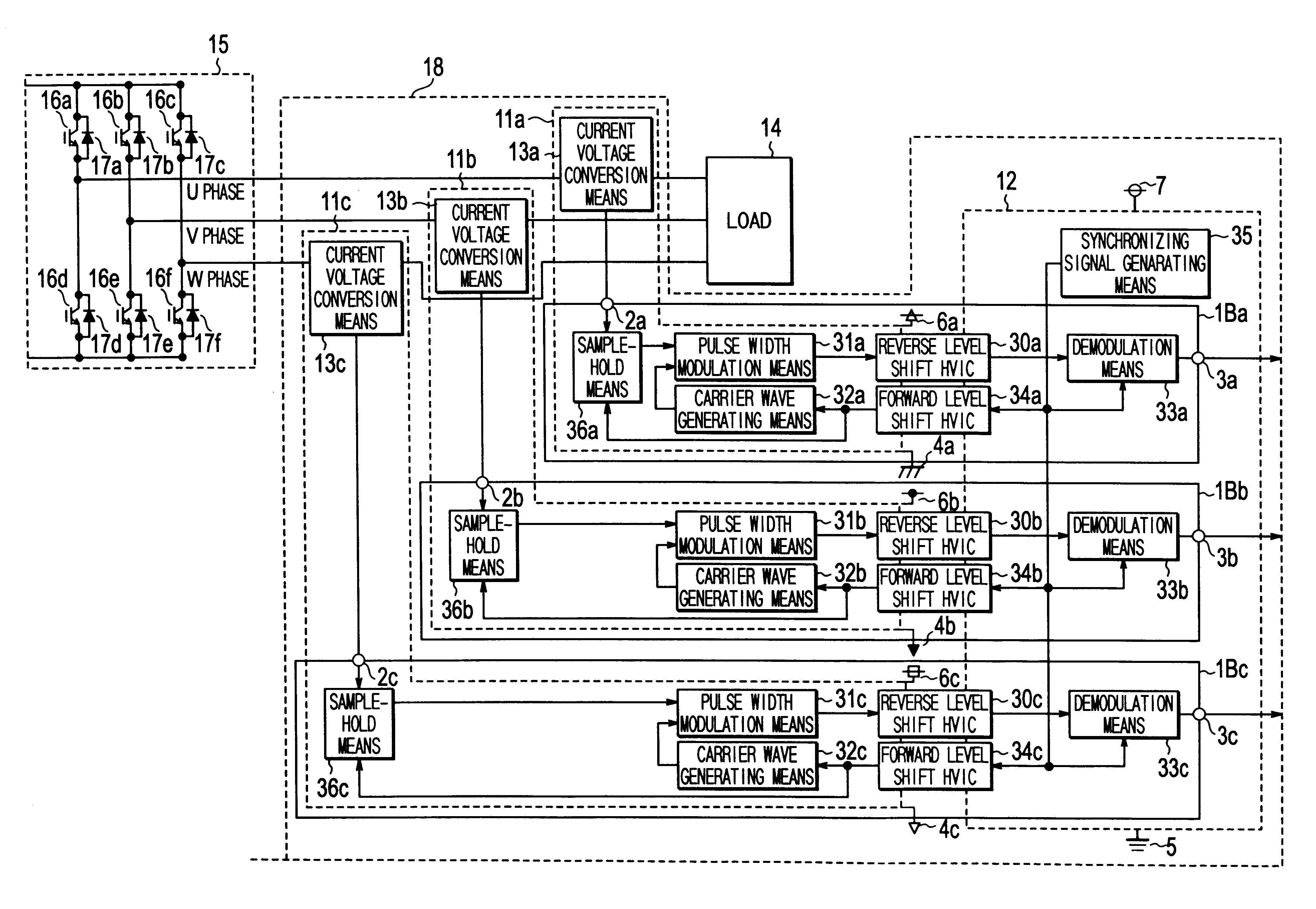
An AC side current detector of a semiconductor power conversion device of embodiment 3 of the invention will be described with reference to the drawings. FIG. 5 is a view showing the structure of the AC side current detector, according to the embodiment 3 of the invention, of the semiconductor power conversion device using the analog signal detecting circuit of the embodiment 2.

In FIG. 5, reference character 1Ba designates a U-phase analog signal detecting circuit; 1Bb, a V-phase analog signal detecting circuit; and 1Bc, a W-phase analog signal detecting circuit.

Besides, in the drawing, reference character 30a designates a U-phase reverse level shift HVIC; 30b, a V-phase reverse level shift HVIC; 30c, a W-phase reverse level shift HVIC; 31a, U-phase pulse width modulation means; 31b, V-phase pulse width modulation means; 31c, W-phase pulse width modulation means; 32a, U-phase carrier wave generating means; 32b, V-phase carrier wave generating means; 32c, W-phase carrier wave generat...


PUM


Abstract

Conventionally, there is a problem that it is impossible to provide an analog signal detecting circuit having high reliability and long lifetime under a bad environment since a photocoupler is used for electrical insulation of a digital signal. Then, an analog signal detecting circuit is provided with a carrier wave generating unit for generating a carrier wave, a pulse width modulating unit for pulse width modulating an analog signal inputted from the signal input terminal by using the carrier wave generated by the carrier wave generating unit and for outputting a digital signal, a reverse level shift HVIC for transmitting the digital signal from one power supply system to the other power supply system, and a demodulation unit for demodulating the digital signal transmitted to the other power supply system into an analog signal and for outputting it to a signal output terminal. As a result, even in the case where reference potentials are different from each other at signal input/output terminals, an analog signal can be detected.

Description

BACKGROUND OF THE TNVENTTON1. Field of the InventionThe present invention relates to an analog signal detecting circuit in which reference potentials at signal input / output terminals are different from each other, and an AC side current detector of a semiconductor power conversion device using the same, and particularly, to an analog signal detecting circuit using a HVIC (High Voltage Integrated Circuit) characterized by including a non-optical semiconductor element, and a dead time fixing method of input / output signals.2. Description of the Related ArtA conventional analog signal detecting circuit will be described with reference to the drawings. FIG. 6 is a view showing a structure of a conventional analog signal detecting circuit. FIG. 6 shows an example of the conventionally used analog signal detecting circuit in which reference potentials at signal input / output terminals are different from each other.In FIG. 6, reference numeral 1 designates an analog signal detecting circuit;...

Claims


Application Information

Patent Timeline
IPC IPC(8): G01R19/25H02M7/5387G01R31/42G01R31/40G01R19/00H02M7/48
CPCG01R19/2513H02M7/53875G01R31/42H02M2001/0009H02M1/0009
Inventor KURAMOTO, YUUJIMAEKAWA, HIROTOSHIANZAI, KIYOHARU
Owner MITSUBISHI ELECTRIC CORP
Why Eureka
Try Eureka