
Zoom lens system

a zoom lens and lens diameter technology, applied in the field of zoom lens systems, can solve the problems of difficult to achieve a further reduction in the diameter of the lens, insufficient zoom lens systems for zoom lens systems having a lower zoom ratio, and large siz

Inactive Publication Date: 2001-02-06
OLYMPUS CORP
View PDF12 Cites 77 Cited by
  • Summary
  • Abstract
  • Description
  • Claims
  • Application Information

AI Technical Summary

Benefits of technology

Another particular object of the present invention is to use a reduced number of lenses thereby achieving a compact zoom lens best suited for use with digital cameras, etc. This zoom lens system is designed to achieve a substantially telecentric emergent bundle while taking an image pickup element such as a CCD into consideration, and obtain such a back focus as to allow optical elements such as low-pass filters and bundle-splitting elements to be located in the system, if required. In addition, the capability of the zoom lens system to form images is considerably improved.
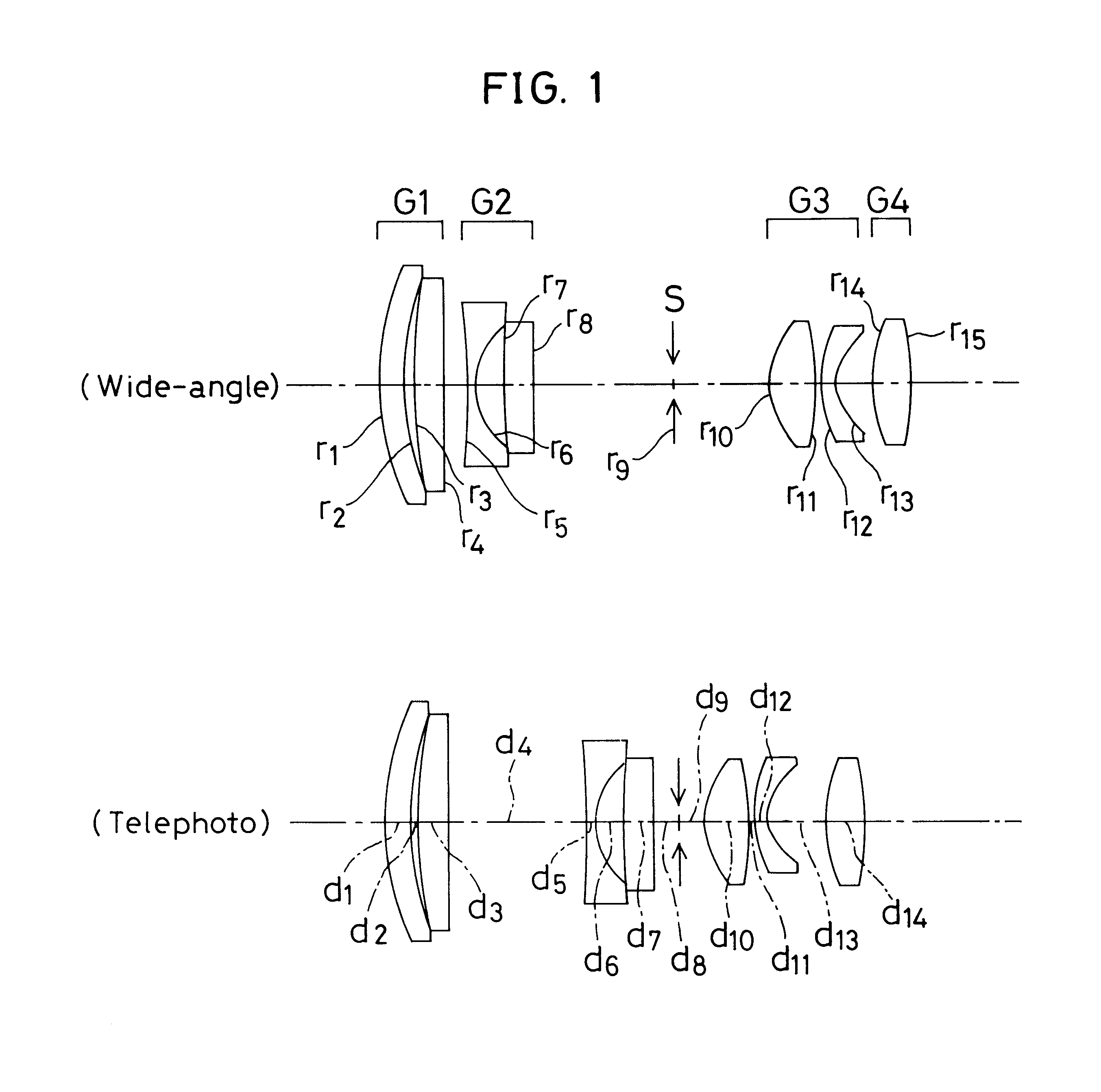
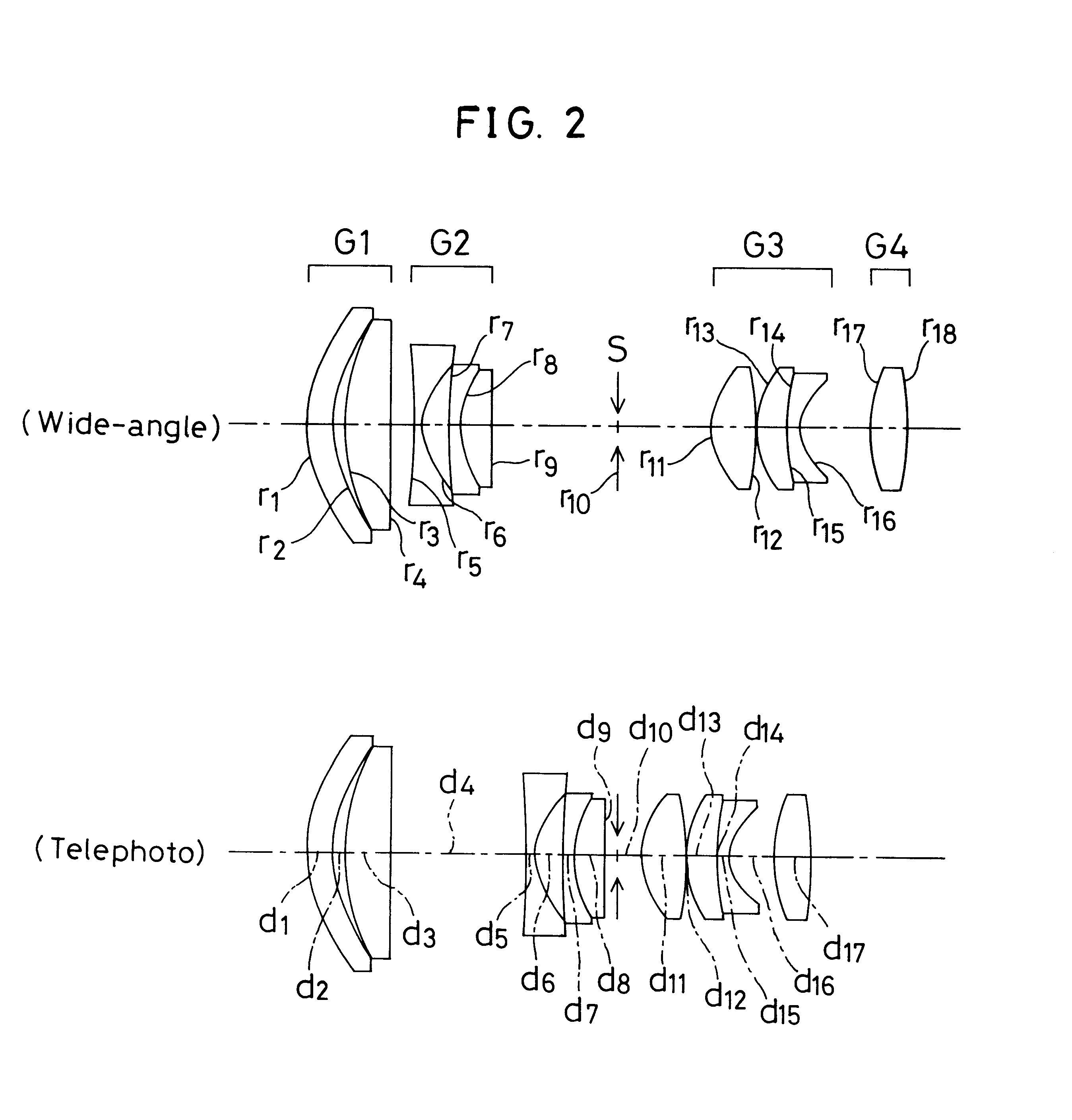
In this embodiment, the first lens group is constructed of two lenses, i.e., a positive lens and a negative lens, whereby chromatic aberrations produced at the first lens group can be reduced irrespective of the power of the first lens group. This in turn allows the subsequent burden of correction of aberrations to be relieved, resulting in a size reduction of the optical system. By using the doublet consisting of a positive lens and a negative lens in the second or third lens group, it is then possible to reduce chromatic aberrations produced at other lens groups and prevent a deterioration in the image-forming capability due to decentration, etc. Consequently, it is possible to achieve an optical system favorable in view of the number of lenses, fabrication cost, and size reductions.

Problems solved by technology

However, these zoom lens systems are still insufficient for zoom lens systems having a lower zoom ratio while weight is placed on ever smaller size and ever lower cost, because of a large number of lenses.
This in turn makes it difficult to achieve a further reduction in the lens diameter, because the height of a ray having the largest field angle and passing through the first lens group cannot be lowered.
This in turn causes the burden of the zooming action on the first and second lens groups to become large, making sufficient size reductions difficult.
Further, spherical aberrations, coma, astigmatism, etc. produced at the third lens group are likely to become large and, accordingly, fluctuations in various aberrations due to the zooming movement of the third lens group are likely to become large.
This in turn causes coma and astigmatism produced at the fourth lens group to become large.
When the lower limit of 0.3 in condition (a) is not reached, the zooming action shared by the third lens group becomes too slender or the burden on the second lens group becomes too large, resulting in a deterioration in aberrations or failing to achieve compactness.
When the upper limit of 1.0 is exceeded, on the other hand, the burden on the third lens group becomes too large, again resulting in a deterioration in aberrations.
With this, the amount of movement of the second lens group to keep the image plane at a constant position becomes large, failing to achieve compactness.
When the upper limit of 1.2 is exceeded or when the power of the third lens group with respect to the second lens group becomes too strong, the amount of astigmatism produced at the third lens group becomes too large, and the distance between the third lens group and an object point therefor becomes too short.
This in turn makes it impossible to provide a sufficient space between the second and third lens groups.
Exceeding the upper limit of 1 is again not preferable because the amount of movement of the third lens group with respect to the second lens group increases with the results that there is an excessive fluctuation in astigmatism, coma and other aberrations produced at the third lens group during zooming while the distance between the third lens group and an object point therefor at the telephoto end becomes too short.
Consequently, no sufficient space can be provided between the second and third lens groups.
This is because the composite focal length of the third and fourth lens groups at the wide-angle end becomes small relative to the radius of the image circle with the results that astigmatism produced at the third and fourth lens groups becomes too large, while the distance between the third lens group and an object point therefor becomes too short.
Consequently, no sufficient space can be provided between the second and third lens groups.
Falling below the lower limit of 0.3 in condition (5) is not preferable because the ratio of the focal length of the third lens group with respect to the focal length of the fourth lens group becomes small, with the results that the power of the fourth lens group becomes too weak, and the amount of movement of the fourth lens group for focusing becomes too large.
When the lower limit of 0.4 is not reached or when the absolute value of the lateral magnification of the second lens group at the telephoto end becomes small, no lens compactness can be achieved because the zooming action of the second lens group becomes insufficient, and the power of the first lens group becomes too weak.
When the upper limit of 1 is exceeded or when the absolute value of the lateral magnification of the second lens group at the telephoto end becomes large, no compactness can again be achieved because the zooming action of the third lens group becomes insufficient, and the power of the first lens group becomes too strong, resulting an increase in the size of the lens system in the first lens group.
The performance of the convex surfaces (opposing to the object side) of the two positive lenses having strong refracting power and the performance of the concave surface (opposing to the image side) of the negative lens are often adversely affected by an error of decentration of such lenses with respect to optical axes at the time of lens fabrication.
Relative decentration between the positive and negative lenses gives rise to a considerable deterioration in the image-forming capability.
Relative decentration between the positive and negative lenses then gives rise to a considerable deterioration in the image-forming capability.
Although the burden of zooming on the second lens group is reduced, yet the burden on the second lens group of correction of aberrational fluctuations in association with zooming is still heavy because the second lens group is a group movable during zooming.
Relative decentration between the positive and negative lenses then gives rise to a considerable deterioration in the image-forming capability.
When the upper limit of 20 is exceeded, on the other hand, the power of the first lens group becomes weak, failing to obtain a satisfactory zoom ratio or achieve size reductions.

Method used


Image

  • Zoom lens system
  • Zoom lens system
  • Zoom lens system

Examples


example 7

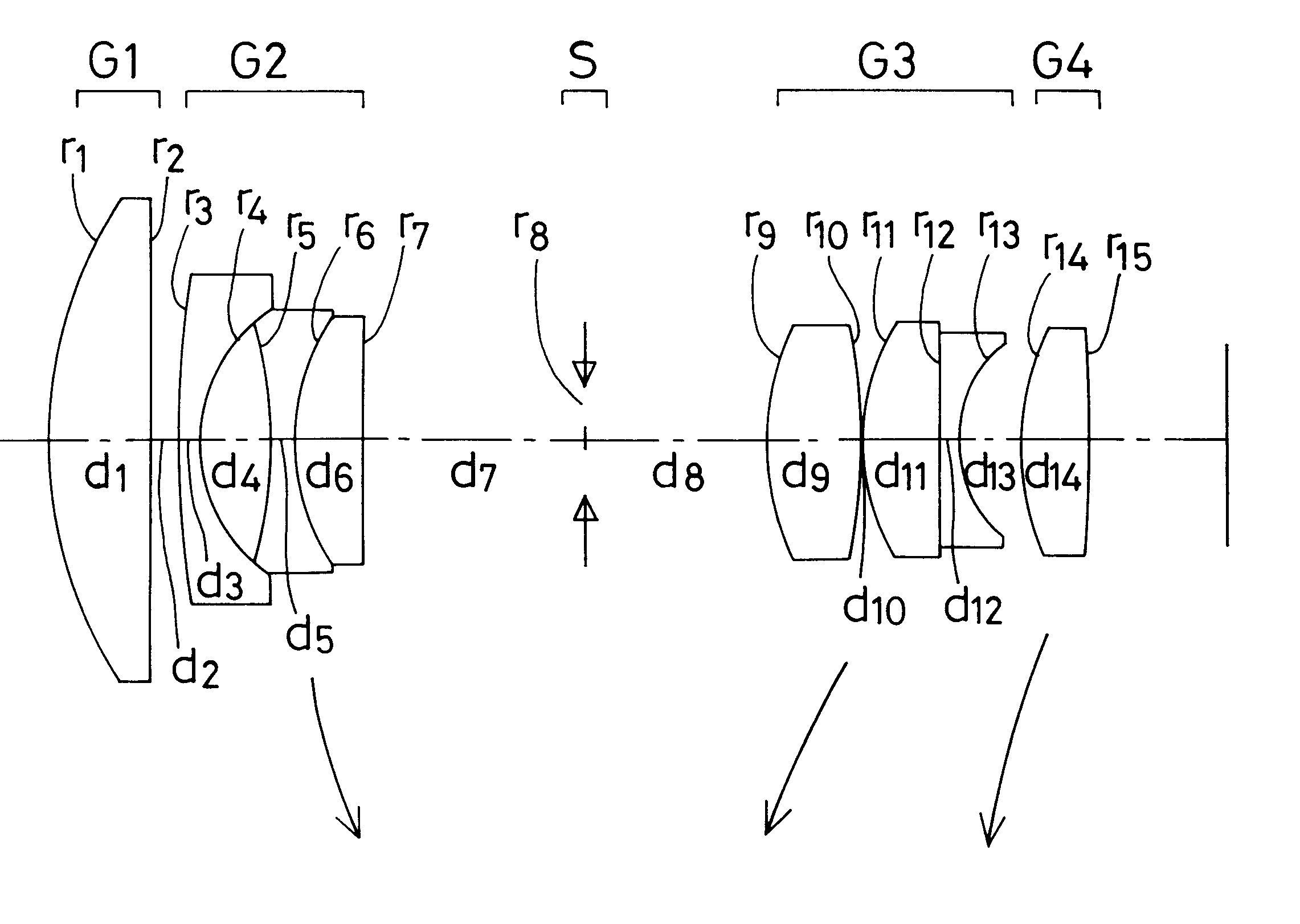
is directed to a zoom lens system having a focal length of 5.50 to 15.75 and a field angle of 66.42.degree. to 24.degree.. As illustrated in FIG. 7, a first lens group G1 is made up of a doublet consisting of a negative meniscus lens convex on an object side thereof and a double-convex lens, and a positive meniscus lens convex on an object side thereof. A second lens group G2 is made up of a negative meniscus lens convex on an object side thereof and a doublet consisting of a double-concave lens and a double-convex lens. At the rear of the second lens group G2 there is located a stop S. A third lens group G3 is made up of two double-convex lenses, and a negative meniscus lens convex on an object side thereof, and a fourth lens group G4 is made up of one positive meniscus lens convex on an object side thereof. An aspherical surface is used for a surface in the third lens group G3 that is located nearest to the object side. For zooming from the wide-angle end to the telephoto end, whi...

example 8

is directed to a zoom lens system having a focal length of 5.52 to 15.91 and a field angle of 67.04.degree. to 23.72.degree.. As shown in FIG. 8, a first lens group G1 is made up of a doublet consisting of a negative meniscus lens convex on an object side thereof and a positive meniscus lens. A second lens group G2 is made up of a negative meniscus lens convex on an object side thereof, a double-concave lens, and a positive meniscus lens convex on an object side thereof. At the rear of the second lens group G2 there is located a stop S. A third lens group G3 is made up of two double-convex lenses, and a negative meniscus lens convex on an object side thereof, and a fourth lens group G4 is made up of one double-convex lens. An aspherical surface is used for the surface in the third lens group G3 that is located nearest to the object side. For zooming from the wide-angle end to the telephoto end, while the first lens group G1 and the stop S remain fixed, the second lens group G2 moves...

example 9

is directed to a zoom lens system having a focal length of 5.50 to 15.81 and a field angle of 66.82.degree. to 23.88.degree.. As can be seen from FIG. 9, a first lens group G1 is made up of a doublet consisting of a negative meniscus lens convex on an object side thereof and a double-convex lens. A second lens group G2 is made up of a double-concave lens and a positive lens, and at the rear thereof there is located a stop S. A third lens group G3 is made up of a double-convex lens, a positive meniscus lens convex on an object side thereof, and a negative meniscus lens convex on an object side thereof, and a fourth lens group G4 is made up of one positive meniscus lens convex on an object side thereof. Three aspherical surfaces are used, one for the surface in the second lens group G2 that is located nearest to the image plane side, one for the surface in the third lens group G3 that is located nearest to the object side, and one for the surface in the fourth lens group G4 that is lo...


PUM


Abstract

The invention provides a zoom lens system that is reduced in terms of both size and cost. The zoom lens system comprises a first positive lens group G1, a second negative lens group G2, a stop S, a third positive lens group G3 and a fourth positive lens group G4. During zooming from a wide-angle end to a telephoto end of the system, while the first lens group G1 remains fixed, the second lens group G2 moves from an object side to an image plane side of the system, the third lens group G3 moves from the image plane side to the object side, and the fourth lens group G4 moves to keep an image plane at a constant position. The first lens group G1 is made up of a negative meniscus lens convex on an object side and a double-convex lens, the second lens group G2 is made up of a double-concave lens and a positive meniscus lens convex on an object side thereof, with an aspherical surface being used for a surface of the positive meniscus lens that is located on an image side thereof, the third lens group G3 is made up of a double-convex lens and a negative meniscus lens convex on an object side thereof, with an aspherical surface being used for a surface of the double-convex lens that is located on an object side thereof, and the fourth lens group G4 is made up of one double-convex lens.

Description

1. Field of the InventionThe present invention relates generally to a zoom lens system, and more particularly to a compact yet low-cost zoom lens system used with cameras using an electronic image pickup means such as camcorders, digital cameras, etc.2. Discussion of Related ArtTo achieve size and weight reductions of a consumer-oriented zoom lens system in this field, a specific zoom lens system has been proposed, which comprises four lens groups, i.e., a positive lens group, a negative lens group, a positive lens group and a positive lens group in order from an object side thereof, as typically disclosed in JP-A's 4-43311 and 4-78806. For zooming, the second negative lens group moves on an optical axis while the first and third lens groups remain fixed. The fourth lens group moves to make correction for a fluctuation in the position of an image plane in association with zooming. A further size reduction is achievable by a specific zoom lens system wherein, as typically disclosed i...

Claims


Application Information

Patent Timeline
Patent Type & Authority Patents(United States)
IPC IPC(8): G02B15/163G02B15/173
CPCG02B15/173G02B15/144113
Inventor ISHII, ATSUJIROMIYAUCHI, YUJI
Owner OLYMPUS CORP
Learn More