
Maneuverable snowshoe

a snowshoe and maneuverable technology, applied in the field of snowshoe construction, to achieve the effect of improving maneuverability

Inactive Publication Date: 2001-02-13
PRIDE INDS
View PDF8 Cites 15 Cited by
  • Summary
  • Abstract
  • Description
  • Claims
  • Application Information

AI Technical Summary

Benefits of technology

This present invention relates to a snowshoe construction and, more particularly, to a lightweight snowshoe providing a user with enhanced maneuverability.
The present invention provides a lightweight snowshoe construction which assures that the user remains highly maneuverable. The snowshoe is designed so that the wearer hardly knows he / she has snowshoes on.

Problems solved by technology

This approach, as well as other approaches, have not resulted in a snowshoe which is commercially acceptable for certain uses.

Method used


Image

  • Maneuverable snowshoe
  • Maneuverable snowshoe
  • Maneuverable snowshoe

Examples


Embodiment Construction

The following, relatively detailed description is provided to satisfy the patent statutes. It will be appreciated by those skilled in the art, though, that various changes and modifications can be made without departing from the invention.

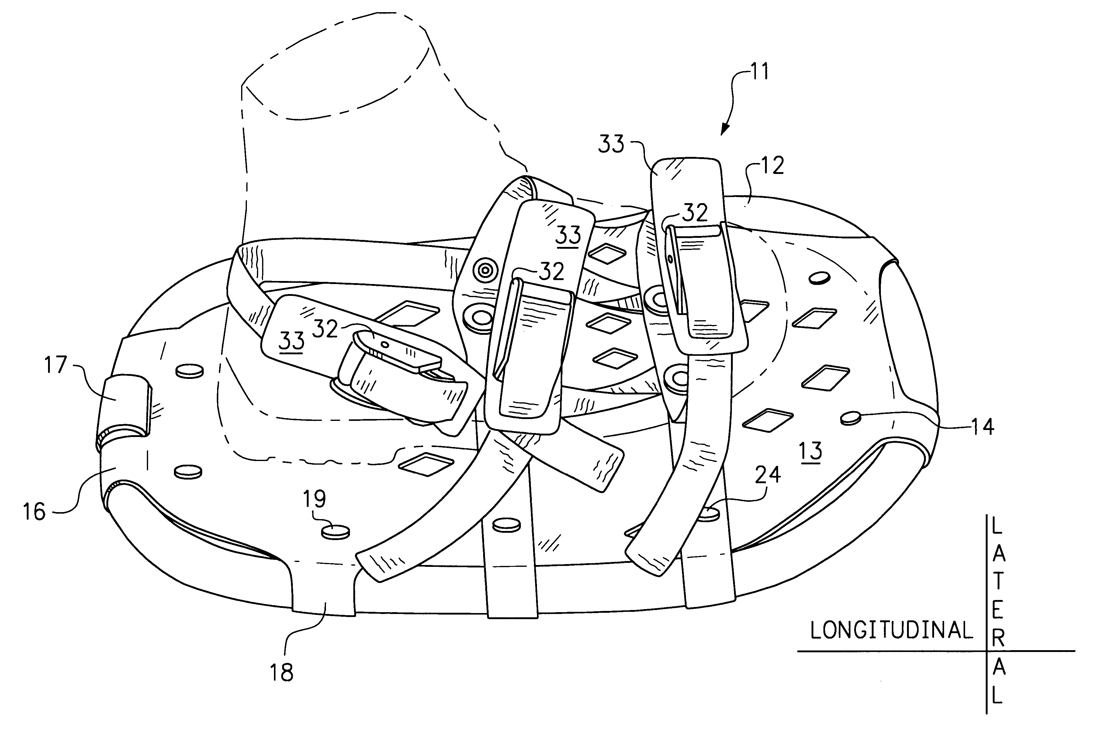
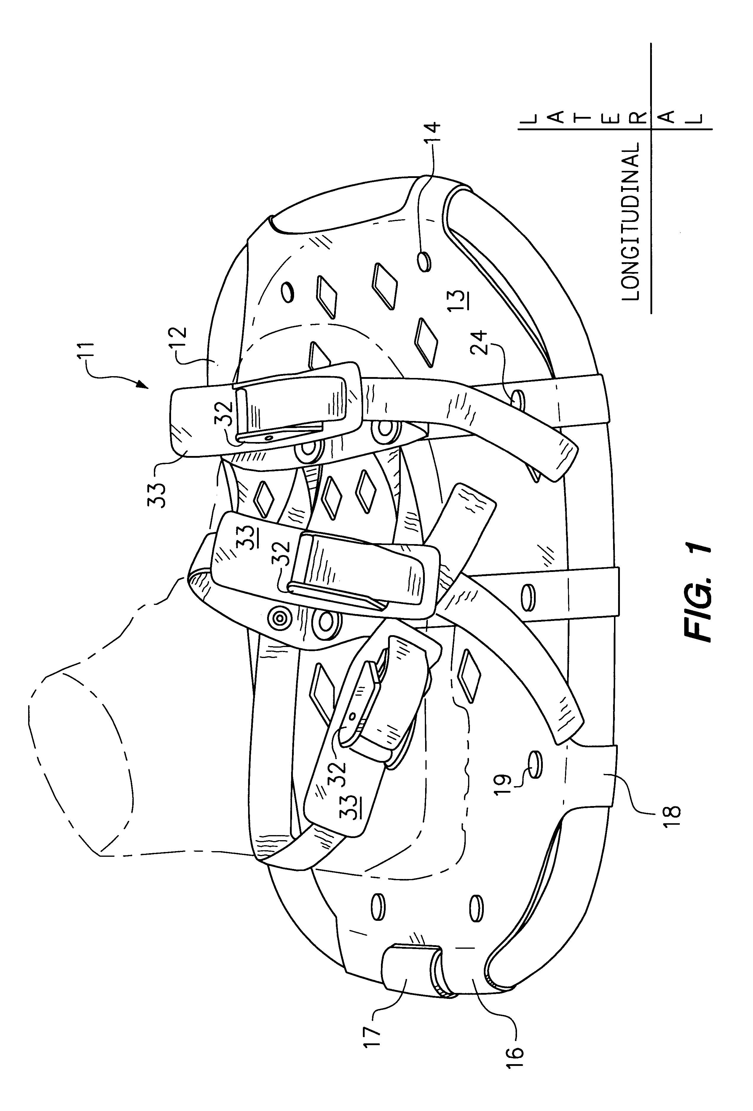
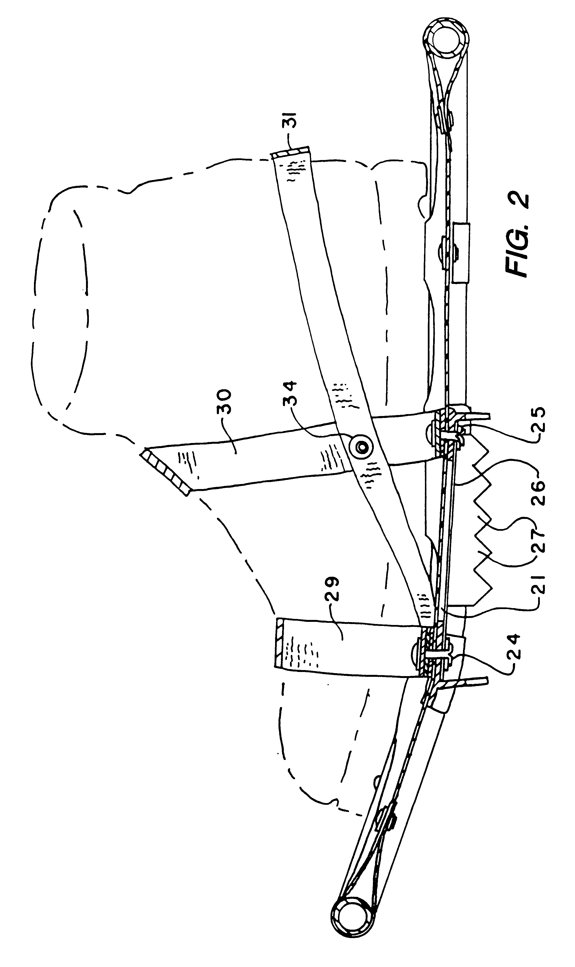
A preferred embodiment of the snowshoe of the invention is generally referred to in the figures by the reference numeral 11. The configuration provided by the snowshoe construction is generally conventional in that it includes a peripheral frame 12 and a membrane decking 13. As is illustrated, the decking 13 extends between the sides of the frame as well as to its front designated by 14 and to its rear designated by 16. In this connection, the frame is a closed loop and its rear is provided by an end coupling 17 which secures together two ends of tubing. The membrane decking can be made of any relatively flexible material typically used for such a purpose. In one implementation the membrane decking was 50 thousandths (50 / 1000) extruded thermoplasti...


PUM


Abstract

A snowshoe is described in which both a simple toe strap and a simple ankle strap are connected to a single, large claw plate, wherein the heel of the user's foot is maintained on an upper surface of the decking.

Description

DISCLOSUREThis present invention relates to a snowshoe construction and, more particularly, to a lightweight snowshoe providing a user with enhanced maneuverability.Because in the past snowshoes have been awkward to use, many design changes to the basic construction have been proposed. Much of the recent effort has been devoted to designing binding arrangements and their securance to the remainder of the snowshoe in such a way as to accommodate the natural stride of an individual, such as by allowing the foot to cant behind the user without the snowshoe itself leaving the ground. In other words, many relatively modern snowshoe designs include an articulating hinge rod or the like to allow the toe of a user to grip the snow (typically with the aid of a crampon) while the heel lifts up from the snowshoe. Examples of this type of shoe construction can be found in U.S. Pat. Nos. 3,517,772 and 5,787,612.This approach, as well as other approaches, have not resulted in a snowshoe which is ...

Claims


Application Information

Patent Timeline
Patent Type & Authority Patents(United States)
IPC IPC(8): A63C13/00
CPCA63C13/001A63C13/005A63C13/006A63C13/003
Inventor NEIDHARDT, JR., GEORGE M.
Owner PRIDE INDS
Learn More