System and method for establishing pitch parameters in a ball-throwing machine

Inactive Publication Date: 2001-02-13
PROBATTER SPORTS
View PDF9 Cites 12 Cited by
  • Summary
  • Abstract
  • Description
  • Claims
  • Application Information

AI Technical Summary

Benefits of technology

, comprises a system and method for establishing pitch parameters in a ball-throwing machine of the type having a power head including three coacting wheels for propelling a ball toward a batter to simulate a pitch. In the preferred embodiment, the speeds of the three wheels are independently controllable so as to control the ball speed, spin rate and spin axis orientation. The pitch parameters correspond to the rotational velocity of each of said wheels and the horizontal and vert

Problems solved by technology

While rotating wheel machines are capable of varying the speed of the pitch and the type of the pitch, an inherent problem with such machines, however, is that they require extensive adjustments and realignment of the machine in order to change from one pitch to another or from one location to another.
Such machines frequently give the hitter a false sense of security, e.g., believing that because they can hit the same pitch delivered repeatedly at the same speed to the same location they will succeed in actual game conditions.
While permitting minor adjustments for both horizontal and vertical position to accommodate for slight changes in pitch speed, none of these patents permit rapid changing of pitch type, i.e., fast ball to curve ball, etc.
The machines described in these patents are not commercial, however, due, in large measure, to their failure to precisely control the horizontal and vertical positioning of the machine.
Moreover, they both fail to carefully consider and control the forces of the three coacting wheels on the ball in order to consistently deliver a variety of different pitches with the accuracy and precision required.
The machine, known as the Triton G-2000, fails to provide for horizontal and vertical adjustments of the aiming point and, as such, is incapable of delivering a plurality of different pitches at different speeds and locations on an interchangeable basis.
Such machines are of the two-wheel type and are incapable of rapid change in order to interchangeably deliver a variety of different pitches.
Accordingly, the degree of programming offered by these devices is minimal, at best.
Furthermore, the ball queuing system of this device relies on gravity and is imprecise and subject to failure.

Method used


Image

  • System and method for establishing pitch parameters in a ball-throwing machine
  • System and method for establishing pitch parameters in a ball-throwing machine
  • System and method for establishing pitch parameters in a ball-throwing machine

Examples


Embodiment Construction

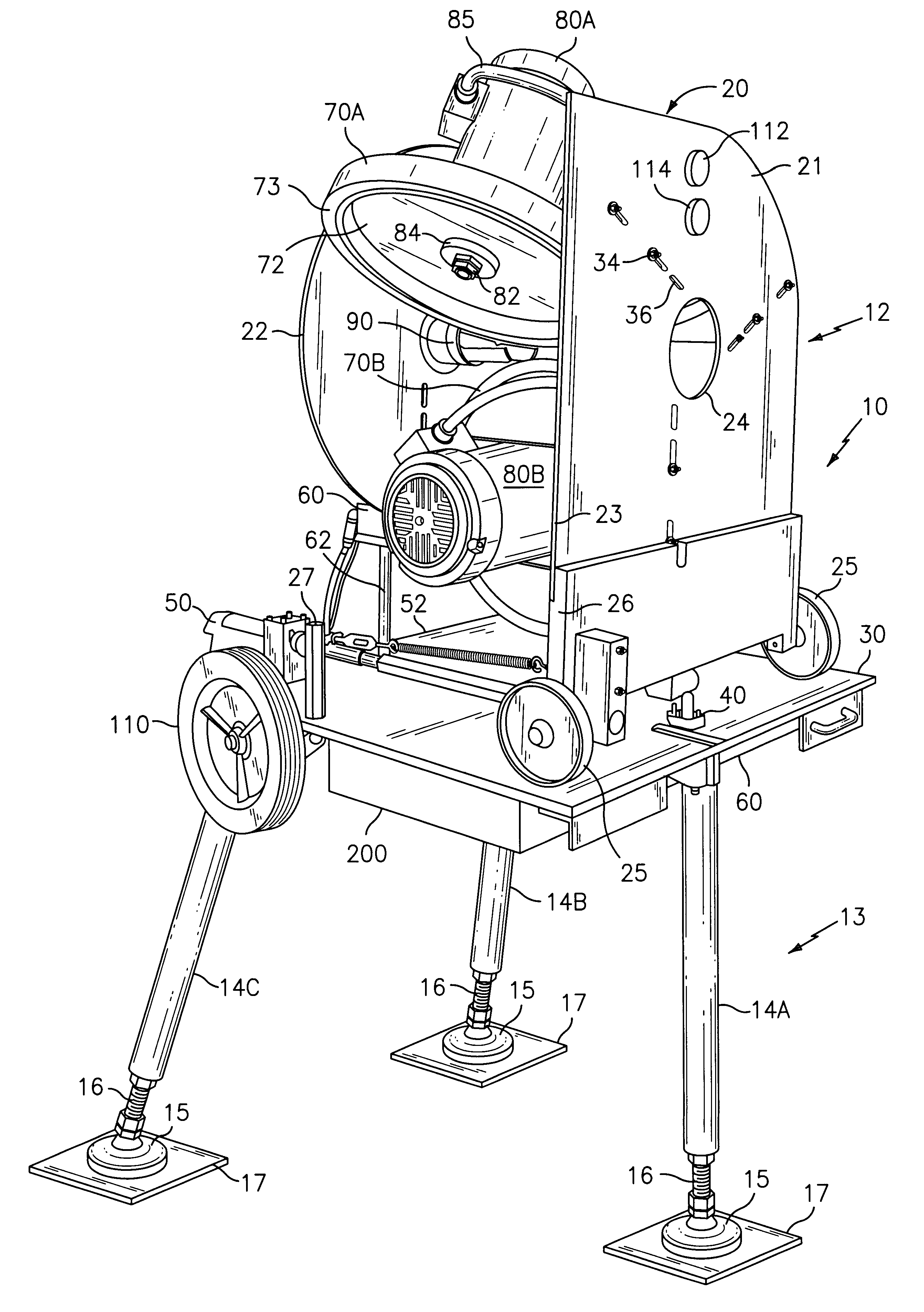
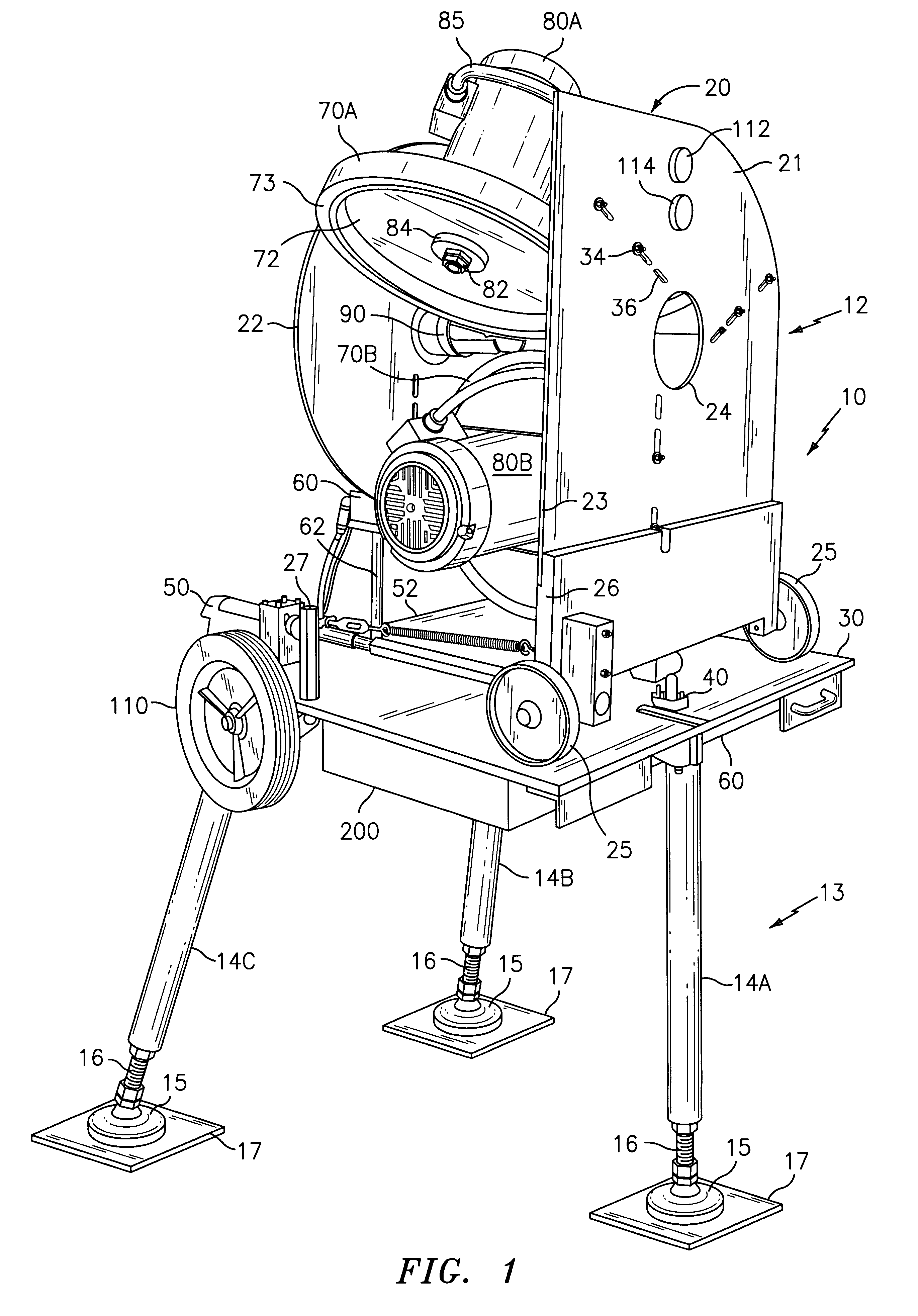
Referring to the drawings and, in particular, to FIG. 1 thereof, the ball-throwing machine of the present invention is provided and is referred to generally by reference numeral 10. The machine 10 includes an upper portion 12 that is mounted on a base 13 that includes a plurality of removable legs 14, preferably a front leg 14A and a pair of rear legs 14B and 14C, respectively, to form a tripod. A shock-absorbing device such as a shock absorber (not shown) may be included in the rear legs 14B and 14C to minimize the impact of any recoil of the machine 10 during use.

An enlarged foot 15 is provided at the outbound end of each leg 14 and is threadably secured to the leg 14 by threaded extension fitting 16 which permits the length of each leg 14 to be increased and decreased. A flat, rubberized plate 17 may be included at the bottom of each foot 15 to provide additional stability for the machine 10, particularly when used indoors such as, for example, on a gymnasium floor. Ball-throwing...


PUM


Abstract

A ball-throwing machine is provided for throwing baseballs, softballs and the like, which machine includes a power head having three coacting wheels for propelling a ball toward a batter to simulate a variety of pitches at different speeds and different locations. Three AC motors and companion motor drives are provided for causing the wheels to rotate at predetermined speeds. The motor drives include dynamic braking circuits to permit rapid deceleration of the wheels. A pair of linear actuators is provided to permit the power head to be moved to predetermined horizontal and vertical positions. The pitches are established by providing a table of five separate data elements for each of said pitches, three of said data elements corresponding to the rotational speed of each of said wheels, and the remaining two data elements corresponding to the horizontal and vertical angular position of the power head. Each of these data elements is computed using a mathematical formula that linearly relates each element to the speed of the ball being propelled. A programmable controller is included for individually controlling the rotational speed of each individual wheel, the horizontal position of the power head and the vertical position of the power head. A smart card reader may be employed for programming of the controller and the machine is adapted to be used in conjunction with a video display to simulate the actual pitching of a baseball by a pitcher. The machine is able to interchangeably deliver pitches of different types to different locations at different speeds with less than ten-second intervals between pitches.

Description

1. Field of the InventionThe present invention relates generally to a ball-throwing machine and, more particularly, to such system and method for establishing pitch parameters in a ball-throwing machine that is adapted to pitch baseballs and softballs and throw tennis and other balls interchangeably to different locations and at different speeds and with different spins, where the ball-throwing machine has a power head having three coacting wheels for propelling a ball toward a batter to interchangeably simulate pitches of different types to different locations at different speeds. Each of these pitch parameters correspond to the rotational velocity of the drive wheels and the horizontal and vertical angular positions of the machine. Each parameter may be computed using a mathematical formula that linearly relates the parameter to the speed of the ball being propelled. The invention has particular applicability as a baseball pitching machine for both professional and amateur athlete...

Claims


Application Information

Patent Timeline
IPC IPC(8): A63B69/40G09B19/00A63B69/00A63B69/38
CPCA63B69/406G09B19/0038A63B69/38A63B2069/0008A63B2069/402A63B2225/15
Inventor BATTERSBY, GREGORY J.GRIMES, CHARLES W.GELDERN, STEVE VAN
Owner PROBATTER SPORTS
Why Eureka
Try Eureka