
Multiple pump sequencing controller

a sequencing controller and pump technology, applied in the field of sequencing controllers, can solve the problems of failure to sound an alarm, the safe switch will not be tripped, and the field cannot leach enough water to support the entire system,

Inactive Publication Date: 2001-02-13
AMERICAN MFG
View PDF15 Cites 23 Cited by
  • Summary
  • Abstract
  • Description
  • Claims
  • Application Information

AI Technical Summary

Benefits of technology

It is yet another object of the present invention object of this invention is to allow one or more loads to be manually removed from the sequence without causing a delay in operation.

Problems solved by technology

If the pump fails to operate once the water reaches the upper level and the water continues to rise, a fail safe switch will be tripped sounding an alarm condition.
Often in larger systems one drain field cannot leach enough water to support the entire system.
However, when a given pump selector switch is placed in the off position (generally for maintenance purposes), the operation of the system is delayed until the liquid level reaches the fail safe float switch, causing the lag pump to activate.
Otherwise an interruption in operation will occur each time the given pump is called for but unavailable.
This is obviously an undesirable situation.
First, if the lag pump is not actuated until the liquid level rises above the fail safe float switch, the drain field to which the lag pump pumps may be overdosed by the extra liquid.
This happening on a continual basis may cause flooding damage to the drain field.
Further, typically an alarm is sounded when the liquid reaches the fail safe measure.
Listening to and resetting this alarm each cycle would be annoying to the point where the operator may simply disable the alarm.
In this situation, the pump system may continue to operate in its compromised condition causing damage to the system and possibly complete system failure.

Method used


Image

  • Multiple pump sequencing controller
  • Multiple pump sequencing controller
  • Multiple pump sequencing controller

Examples


Embodiment Construction

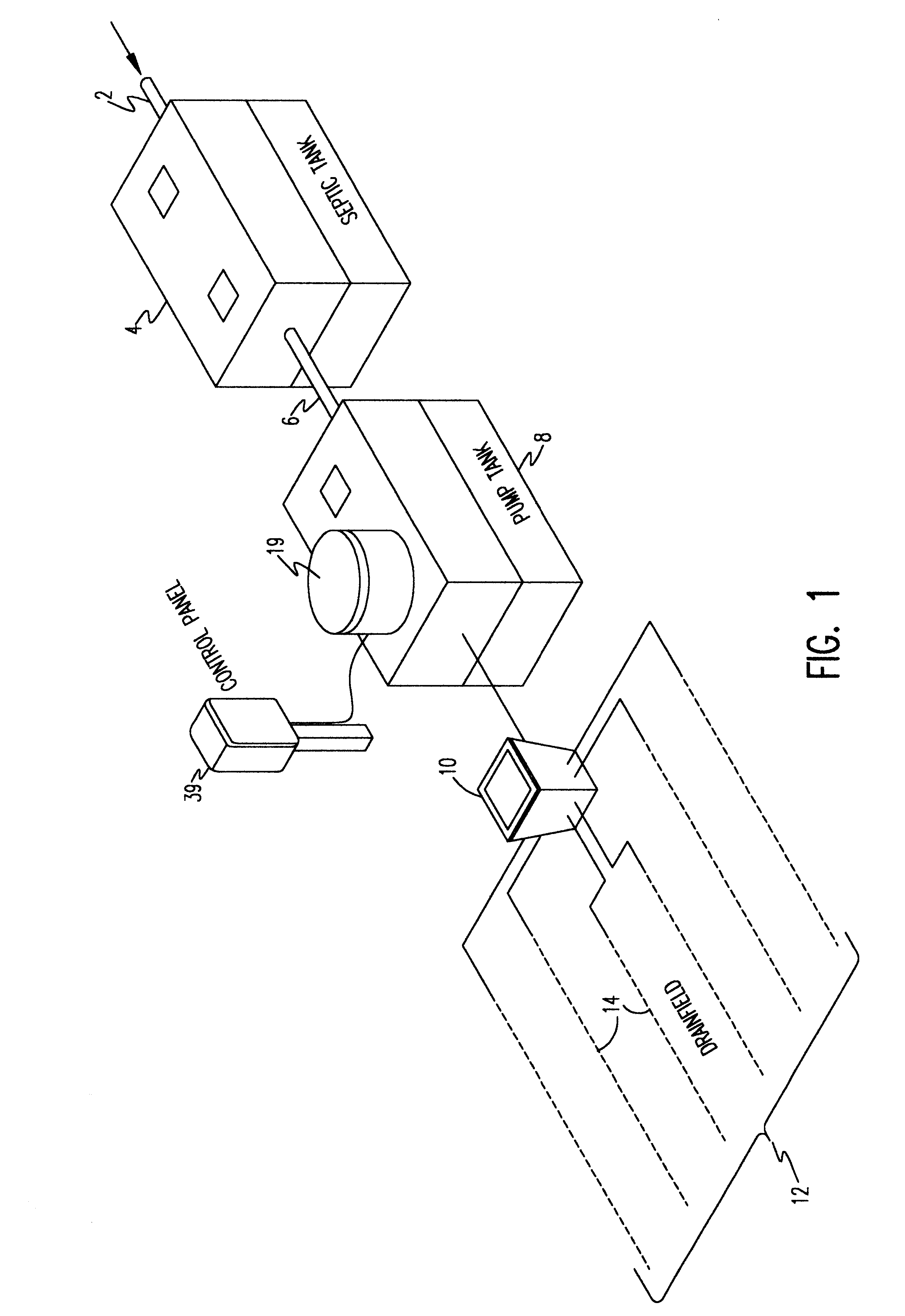
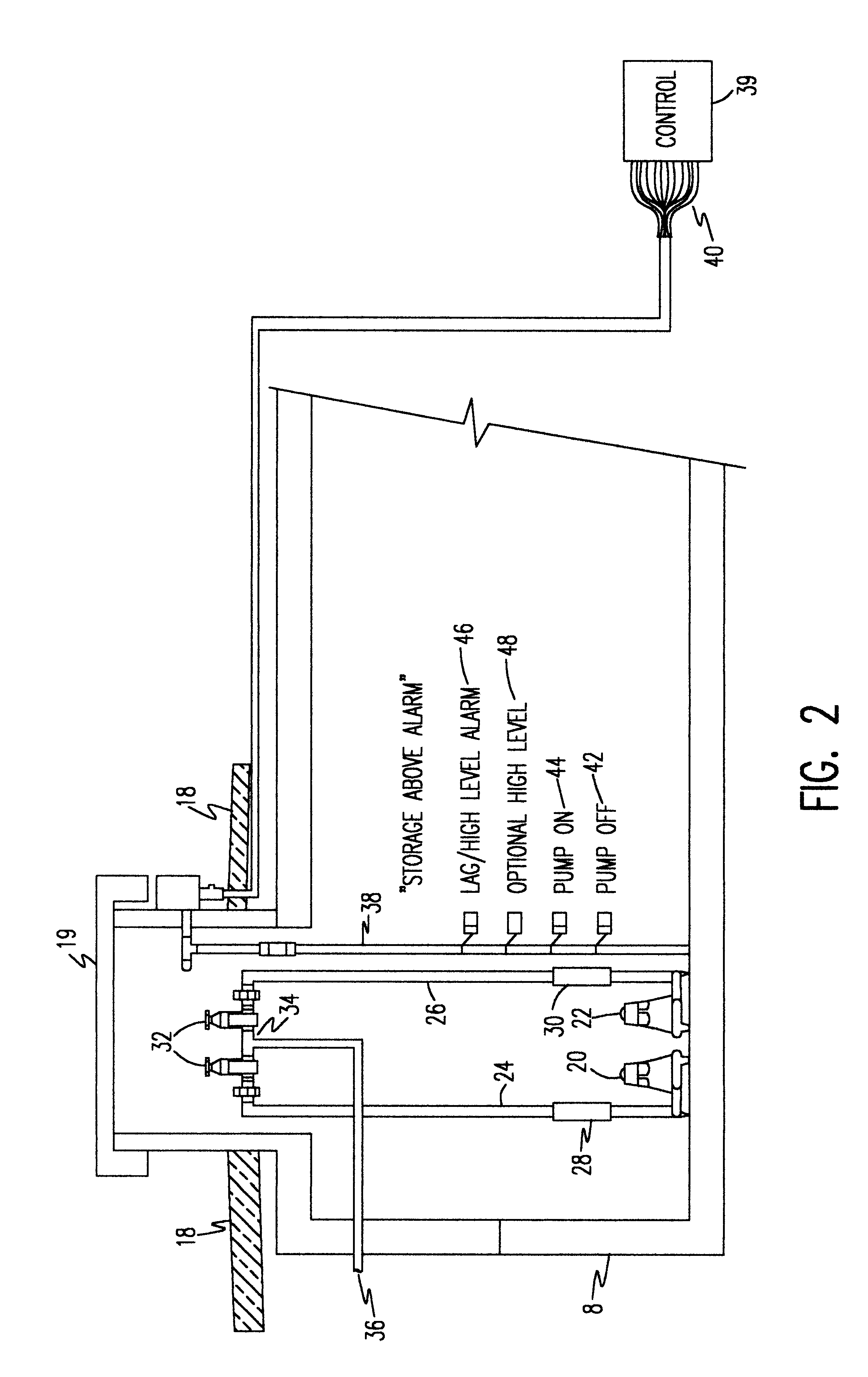
Referring now to the drawings, and more particularly to FIG. 1, there is shown a perspective view of an exemplary on-site septic system. Waste water flows through an inlet 2 and into a treatment tank 4. The treatment tank may be of any suitable type, such as a standard septic tank which acts as an anaerobic holding tank, or it may be an aeration system providing aerobic treatment to the waste water stream, or any other type of treatment system. Solids settle to the bottom of the tank to be broken down by an anaerobic process and clarified water effluent escapes the tank from a pipe 6 to the dosing tank or pump tank 8 which receives the effluent on the demand of the system. The level of effluent in the dosing tank 8 is sensed by the system controller 39 through level switches, as shown in more detail in FIG. 3. When the level of the effluent reaches a predetermined level, pumps (shown in FIG. 2) pump the effluent to a distribution box 10 for distribution to the drain field 12. The dr...


PUM


Abstract

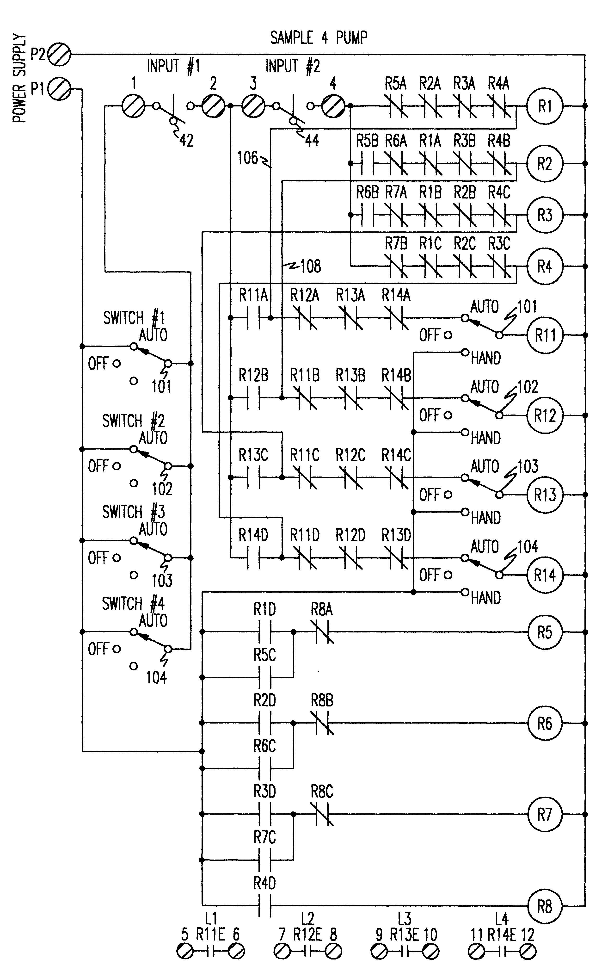
A sequential controller is provided for sequencing multiple electric loads such electric pumps. That is, for each cycle the next load is designated as the lead load in a round-robin fashion. The controller uses cost effective electro-mechanical relay logic an thus avoids conventional solid state technology. In order to sequence the loads on each successive cycle, the electro-mechanical relay connected to the sensors comprises a double-throw contact set. The double-throw contact set comprises two complementary contacts, both of which alternate between normally open and normally closed on each successive cycle. In this manner one each successive cycle, the pumps designated as the lead pump and the lag pump automatically alternate in a round-robin fashion. Further, when the lead pump is disabled the lag pump is immediately actuated without disruption of service.

Description

1. Field of the InventionThe present invention generally relates to a controller for controlling the operational sequence of electrical loads and, more particularly, to a sequencing controller using electro-mechanical relays to control the operational sequence of multiple pumps in, for example, a septic system.2. Description of the Prior ArtThere are many applications for which it is desirable to sequence the operation of multiple electrical loads such as the sequential operation of multiple pumps used for an on-site septic system. In a simple septic system once waste water is ejected from a building it flows through the waste pipe and into a septic tank. Solids settle to the bottom of the tank to be broken down by an anaerobic process and clarified water effluent escapes the tank from an effluent pipe positioned opposite the waste pipe. The effluent is then channeled by a distribution box to various tubes fanned out below the surface of the ground in a drain field where it is allow...

Claims


Application Information

Patent Timeline
Patent Type & Authority Patents(United States)
IPC IPC(8): F04B41/06F04B41/00
CPCF04B41/06F04B2203/0214
Inventor ROMER, KEVIN J.
Owner AMERICAN MFG
Learn More