Bumps in grooves for elastic positioning

a technology of elastic positioning and grooves, applied in the field of electronic devices, can solve the problems of increasing the length of the path between components, unable to offer an elastic high precision self-alignment of a part at a micrometer, and the inability to manufacture parts at a high precision, etc., to achieve stable high-precision parts alignment, high manufacturing reproducibility, changeability and replaceability

Inactive Publication Date: 2001-02-13
INFINEON TECH AG
View PDF26 Cites 32 Cited by
  • Summary
  • Abstract
  • Description
  • Claims
  • Application Information

AI Technical Summary

Benefits of technology

One advantage of the present invention is that continued high precision alignment of parts will be stable when external mechanisms cause effects on the parts.
Another advantage of the present invention is the changeability and replacebility of parts in the advanced packaging system.
Another advantage of the present invention is that the parts can absorb elastic changes and still be aligned along a line in the X-Y plane.
Anothe

Problems solved by technology

When the complexity of a system grows, the length of the paths between components also grows.
For this purpose there is no existing technology offering an elastic high precision self alignment of a part at a micrometer or even sub-micrometer scale.
If parts in the system consist of materials with different thermal expansion coefficients, then solid joints may cause problems due to stresses arising from temperature variations.
For example, thermal expansion may cause severe problems due to displacement of a laser used

Method used


Image

  • Bumps in grooves for elastic positioning
  • Bumps in grooves for elastic positioning
  • Bumps in grooves for elastic positioning

Examples


Embodiment Construction

This invention describes a technology for fast and easy non-permanent elastic self-aligned high precision mounting so that assembling of parts requires only coarse external alignment, while maintaining predefined elasticity to limit stresses due to thermal and other mismatches.

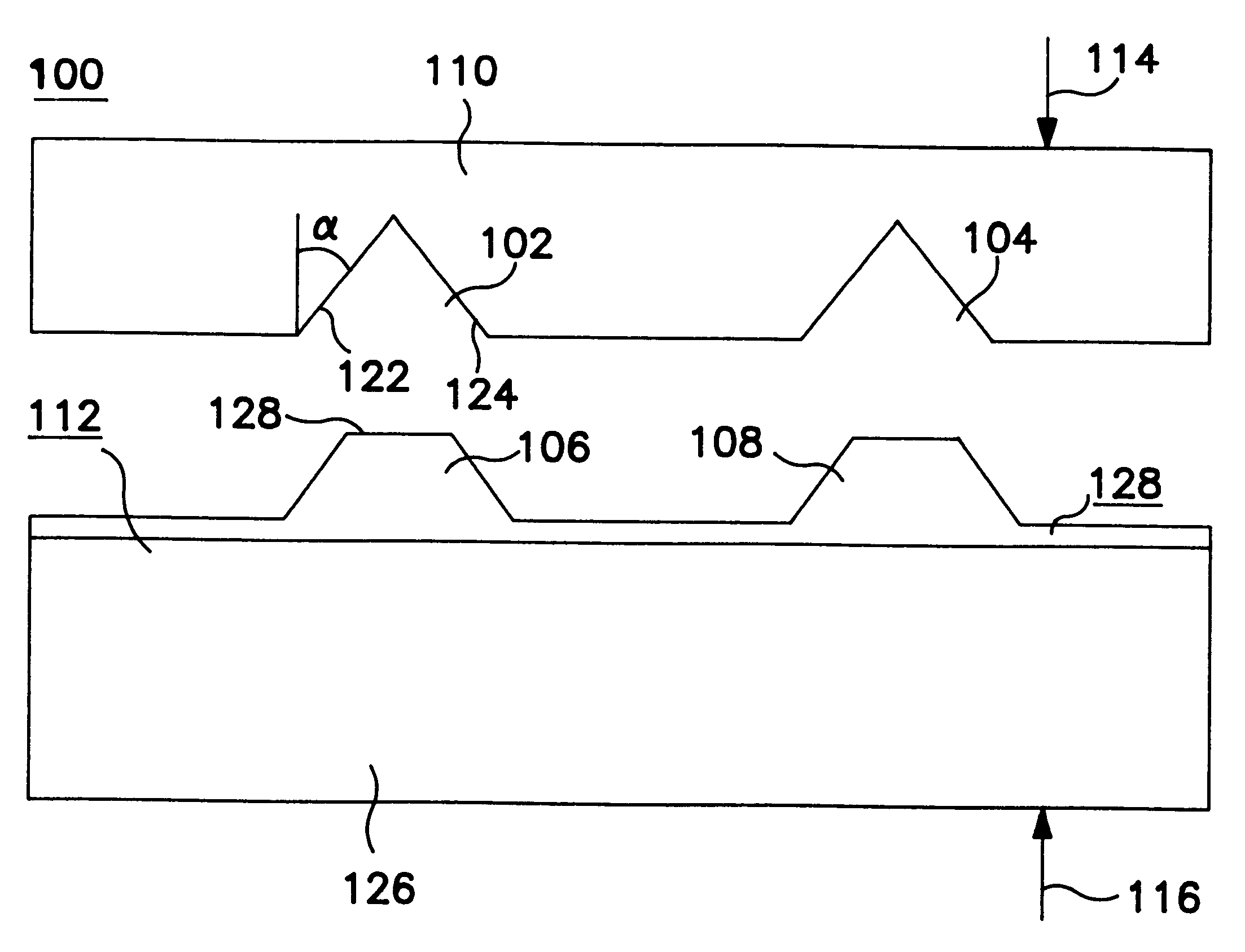
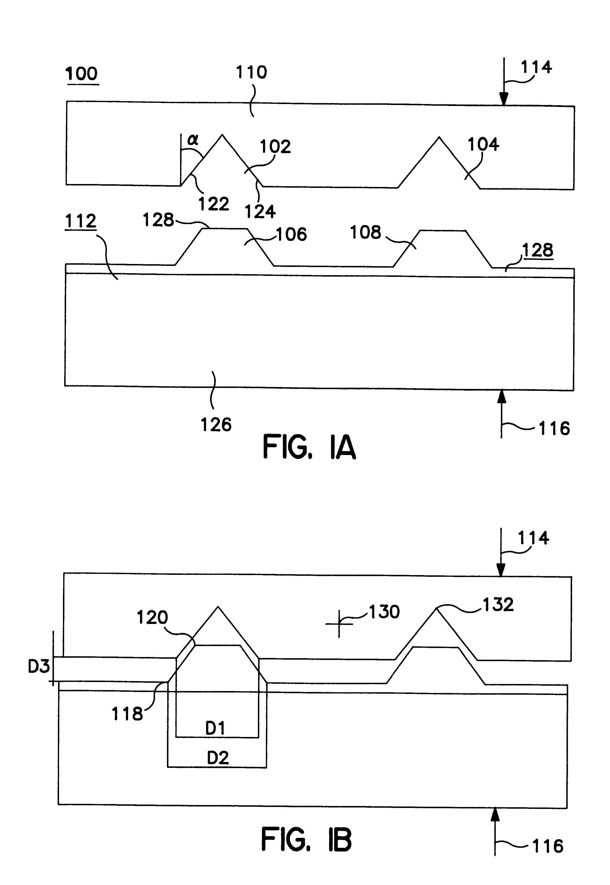
FIG. 1 and FIG. 3 show embodiments of the present invention. This invention can of course be used in any kind of micrometer or even sub-micrometer system. In FIG. 1 there is shown a preferred embodiment of the present invention, an aligning structure 100. FIG. 1a shows a first part 110 with V-grooves 102, 104 moved down to fit moulded bumps 106, 108 on a second part 112. The precision of the positioning is determined by the technology and the materials used to prepare the bumps 106, 108 and the V-grooves 102, 104. The first part 110 is made of, for example, a single crystalline Si-wafer (100), and the second part 112 consists of a substrate 126 and a structure 128 with bumps. The bumps 106, 108 are made of an ...


PUM


Abstract

This invention belong to a mounting technology for aligning parts, a self-aligned elastic positioning. A problem this invention solves is alignment of parts without using mechanical fine pre-alignment. Wherein one part has elastic bumps, another part has V-grooves and the parts fit into each other. The invention is using elastic material for the bumps to fit the V-grooves. Whereas the bumps are made of elastic material and shaped partly to the V-bumps by moulding. The two parts can slide along in the direction perpendicular to the plane of the surface of the part. The movement in the perpendicular direction can be controlled by an external force. This means that the bumps and V-grooves have good alignment in xy-orientation and are also partial aligned in z-orientation. The elasticity of the bumps allows for thermal expansion differences without stresses to the parts while maintaining high precision alignment at a point. By using this type of parts they can be disassembled and be replaced without destroying the alignment features.

Description

The present invention relates to a mounting technology for aligning parts in electronic field, more particularly to a fast and easy self-aligned elastic high precision positioning, where one part has bumps, another part has V-grooves and the parts fit into each other.DESCRIPTION OF RELATED ARTThe technical evolution in the field of electronics, has resulted in a demand for faster and more compact systems. In many applications a compact structure combined with a low weight is in itself a requirement. The technical evolution also tends towards more complex systems involving a greater and greater number of components, which need to communicate with each other. In order to meet the requirement of quick access between different components for the new systems the length of the paths between different components of the system must be kept within certain limits. When the complexity of a system grows, the length of the paths between components also grows. In order not to exceed the maximum a...

Claims


Application Information

Patent Timeline
IPC IPC(8): H01L21/02H01L21/58H01L21/60H01L29/06H01L29/02
CPCH01L24/26H01L24/83H01L29/0657H01L2224/8319H01L2224/8385H01L2924/01005H01L2924/01013H01L2924/01033H01L2924/01039H01L2924/01057H01L2924/01082H01L2924/07802H01L2924/10158H01L2924/14H01L2224/81191H01L2224/81141H01L2924/01006H01L2924/01019H01L2924/0102H01L2924/01023H01L2924/01068H01L2924/014H01L2224/83141H01L2924/12042H01L2924/00H01L25/04
Inventor BODO, PETERHESSELBOM, HJALMAR
Owner INFINEON TECH AG
Why Eureka
Try Eureka