Helical spiral balloon catheter

a balloon catheter and spiral technology, applied in balloon catheters, other medical devices, surgery, etc., can solve the problem that none of those patents discuss the importance, and achieve the effect of improving the flow protection

Inactive Publication Date: 2001-02-20
BERSIN ROBERT M
View PDF6 Cites 145 Cited by
  • Summary
  • Abstract
  • Description
  • Claims
  • Application Information

AI Technical Summary

Benefits of technology

The balloon catheter of the present invention provides a configuration which permits continued perfusion along the main blood vessel in which the medical treatment is being performed, and provides improved protection of flow to side branch blood vessels extending from the main blood vessel, all while the balloons of the catheter are expanded or inflated and are performing their function of cente...

Problems solved by technology

However, none of those patents discuss the importance of ...

Method used


Image

  • Helical spiral balloon catheter
  • Helical spiral balloon catheter
  • Helical spiral balloon catheter

Examples


Embodiment Construction

The present invention is an improvement to the device disclosed and illustrated in U.S. Pat. No. 5,383,856, issued to the same inventor, and that patent is hereby incorporated by reference, in its entirety. The following description of FIGS. 1-7 is essentially identical to that set forth in the aforenoted patent, and is followed by a description of the unique features of the instant invention.

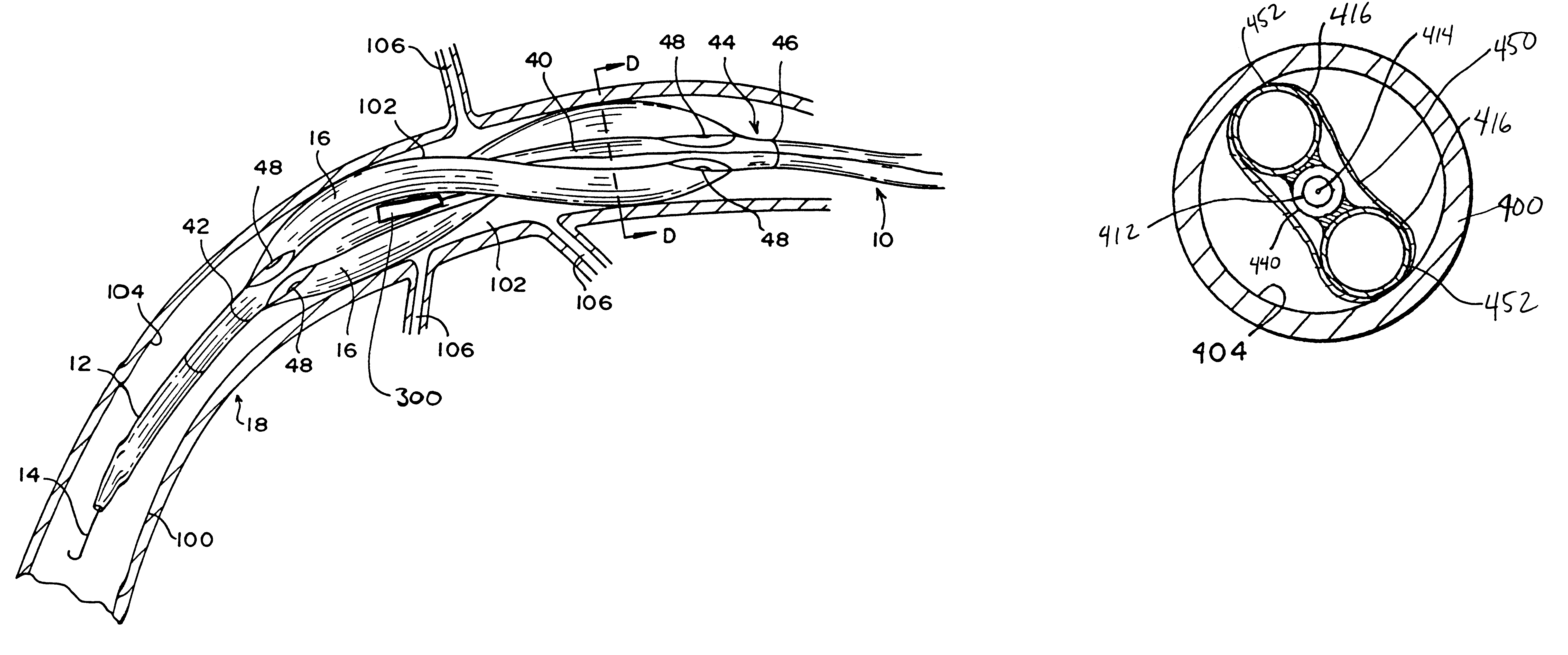
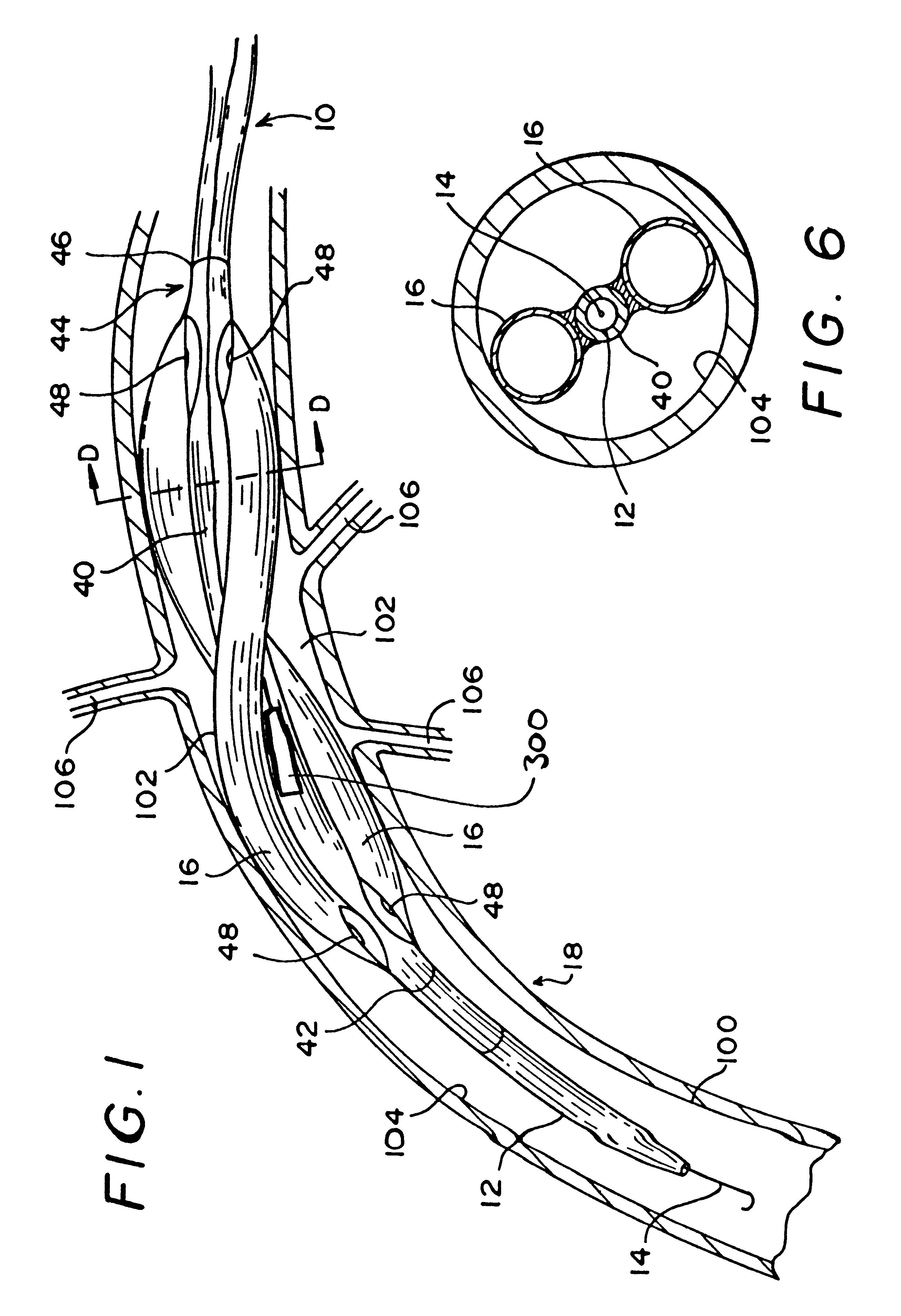
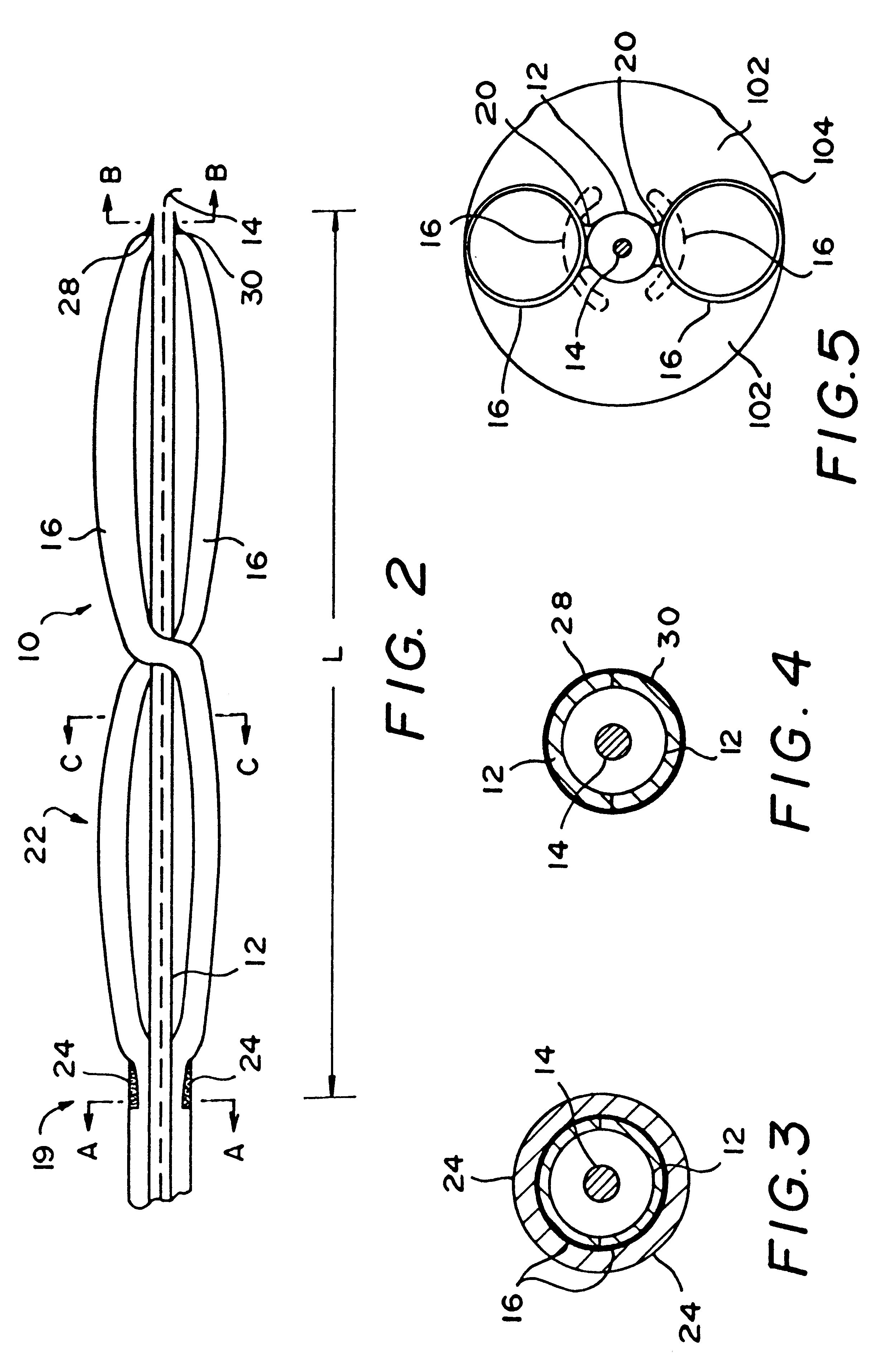
Referring initially to FIGS. 1 and 2, the multiple helical balloon catheter is designated by numeral 10. Catheter 10 has a central support tube defining a central lumen 12 adapted to carry therein a guide or advance wire 14 which, as is generally known in the art, is used to facilitate insertion of the catheter to the desired position within the blood vessel. In the present invention, because the device will be used primarily for repair of dissections in blood vessels, the desired position for the catheter in the blood vessel will ordinarily be at the site where the dissection has occurred and / ...


PUM


Abstract

A balloon catheter device designed to be especially well suited for use in providing medical treatment within a blood vessel, and a method for conducting such medical treatment are provided, wherein the balloon catheter has a central support tube or lumen, and has, near a distal end of the catheter, a plurality of inflatable balloon elements extending along the catheter in helical patterns, with the balloon elements spaced equidistantly around the central support tube. The catheter thus provides the ability to apply pressure, by way of the inflated balloon elements, to center the central support tube in the blood vessel, while at the same time preserving blood flow in the blood vessel past the catheter as well as in side branch blood vessels extending from the blood vessel under repair.

Description

BACKGROUND OF THE INVENTION1. Field of the InventionThe present invention relates to balloon catheters, and more particularly to catheters for use in centering a central support tube in a blood vessel for use in a medical treatment process.2. Description of Related ArtSeveral designs of dilatation balloon catheters have been proposed in the prior art, examples of which can be seen in U.S. Pat. No. 5,160,321; U.S. Pat. No. 5,090,958; U.S. Pat. No. 4,787,388; and U.S. Pat. No. 4,581,017. Each of those balloon dilatation catheters was designed for the purpose of administering treatments to physically widen constricted blood flow passages. The term stenosis is used in this regard to refer to a region of a blood vessel which has been narrowed or constricted to such a degree that blood flow is restricted. In severe instances, treatment of the stenosis is required. Treatment of coronary blood vessels by use of the aforenoted prior art dilatation balloon catheters is referred to in the art ...

Claims


Application Information

Patent Timeline
IPC IPC(8): A61M25/10A61F2/958
CPCA61M25/1002A61M2025/1047
Inventor BERSIN, ROBERT M.
Owner BERSIN ROBERT M
Why Eureka
Try Eureka