Insitu formable and self-forming intravascular flow modifier (IFM) and IFM assembly for deployment of same

a technology of intravascular flow modifier and ifm, which is applied in the field of insitu formable and self-forming intravascular flow modifier (ifm) and/or stent, can solve the problems of inability to deploy most related art devices in intracranial vessels, device configurations having substantially reduced diameters compared to their respective deployed configurations, and are typically too large and too stiff to naviga

Inactive Publication Date: 2001-02-20
MICRUS CORP
View PDF38 Cites 353 Cited by
  • Summary
  • Abstract
  • Description
  • Claims
  • Application Information

AI Technical Summary

Benefits of technology

Another embodiment of the assembly comprises an IFM having a deployed configuration when in the vessel at a site of the defect and a pre-deployed configuration for movement through the vessel towards the site of the defect as discussed above. The assembly also includes a means for moving and maintaining the IFM when in the pre-deployed configuration. The outer and inner layers of the IFM take the deployed configuration when the moving and maintaining means is no longer applied thereto. The moving and maintaining means preferably comprises an elongated first catheter having a size and shape complementary to the respective size and shape of the IFM when in the pre-deploy...

Problems solved by technology

Most related art devices cannot be deployed in intracranial vessels.
Even the devices having a pre-deployed configuration with a substantially reduced diameter compared to the...

Method used


Image

  • Insitu formable and self-forming intravascular flow modifier (IFM) and IFM assembly for deployment of same
  • Insitu formable and self-forming intravascular flow modifier (IFM) and IFM assembly for deployment of same
  • Insitu formable and self-forming intravascular flow modifier (IFM) and IFM assembly for deployment of same

Examples


Embodiment Construction

Reference will now be made in detail to the present preferred embodiments of the invention, examples of which are illustrated in the accompanying drawings.

An intravascular flow modifier (IFM) for use in a vessel according to the present invention comprises an outer layer formed of a strand. The strand is configured as a longitudinally oriented coil of adjacent helical loops extending between a first end and a second end of the outer layer.

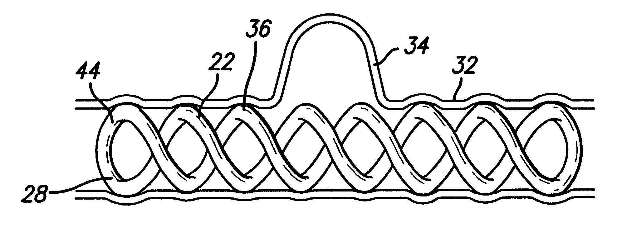
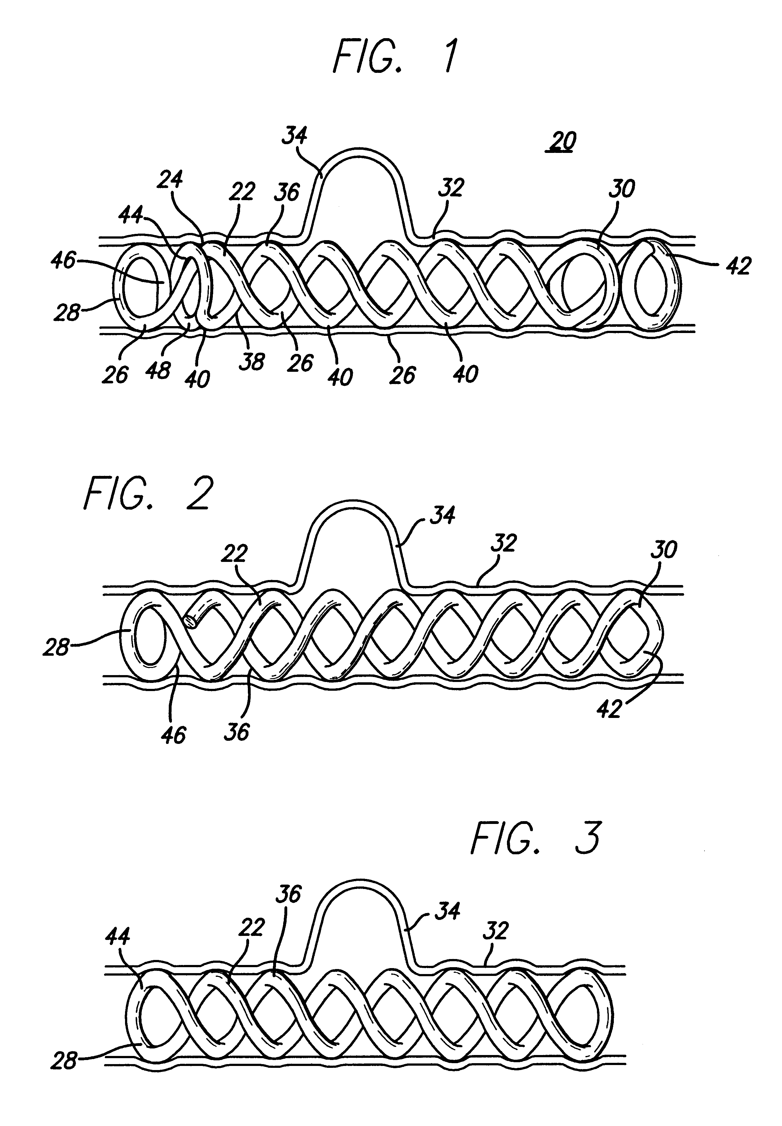
An exemplary embodiment of the IFM of the present invention is shown deployed in a vessel in FIG. 1 and designated generally by reference numeral 20. The shaded segment of IFM is facing the inside of the loop and in this embodiment the outer layer has a beta helix and the inner layer has an alpha helix.

As broadly embodied herein, and referring to FIG. 1, an IFM 20 has an outer layer 22 formed of a strand. The strand is configured as a longitudinally oriented coil 24 of adjacent helical loops 26 extending between a first end 28 and a second end 30 o...


PUM


Abstract

An intravascular flow modifier (IFM) for use in a vessel has an outer layer formed of a strand configured as a longitudinally oriented coil of adjacent helical loops extending between a first end and a second end of the outer layer. The outer layer is secured in the vessel by at least some of the helical loops pressing against a portion of the interior surface of the vessel. The IFM also has an inner layer formed of a strand configured as a longitudinally oriented coil of adjacent helical loops extending between a first end and a second end of the inner layer. At least a portion of the outer layer surrounds at least a portion of the inner layer so that at least some of the loops of the outer layer overlap and contact at least some of the loops of the inner layer An assembly and method for deploying are also disclosed.

Description

1. Field of the InventionThe present invention relates broadly to an insitu formable and self-forming intravascular flow modifier (IFM) and / or stent and the delivery and deployment of the IFM to a defect in a vessel. More particularly, the invention relates to an IFM that may be deployed in previously inaccessible vessels to current generation IFMs or stents due to the nearly linear pre-deployed configuration of the IFM and a method for controlling the final placement and deployed configuration of the IFM within a pre-selected segment of the vessel. The present invention is particularly suited but not limited to use as an intracranial IFM and method for deploying the IFM in a vessel.2. Description of the Related ArtMost related art devices cannot be deployed in intracranial vessels. Even the devices having a pre-deployed configuration with a substantially reduced diameter compared to their respective deployed configuration are typically too large and too stiff to navigate the tight ...

Claims


Application Information

Patent Timeline
IPC IPC(8): A61F2/01A61F2/06A61B17/12A61F2/00A61F2/88
CPCA61B17/12118A61F2/01A61F2/88A61F2/95A61B17/12022A61F2/0077A61F2/30767A61F2002/011A61F2002/016A61F2002/068A61F2002/30093A61F2002/30125A61F2002/30153A61F2002/30156A61F2002/30199A61F2210/0019A61F2230/0008A61F2230/0019A61F2230/0023A61F2230/0063A61F2230/0006A61F2230/0091A61F2002/30092A61F2/011
Inventor HORTON, JOSEPH A.VINCENT, DIANA JOAN
Owner MICRUS CORP
Why Eureka
Try Eureka