
Vehicle-air-conditioning system with cooling degree estimator for left/right temperature control

a technology of vehicle air conditioner and degree estimator, which is applied in the direction of domestic cooling apparatus, heating types, instruments, etc., can solve the problems of increasing the number of system parts, system cost, and inability to independently control the air flow rate,

Inactive Publication Date: 2001-02-27
DENSO CORP
View PDF8 Cites 77 Cited by
  • Summary
  • Abstract
  • Description
  • Claims
  • Application Information

AI Technical Summary

Benefits of technology

It is an another object of the present invention to provide a vehicle air-conditioning system which prevents frosting of a cooling heat exchanger while preventing a windshield from being fogged.
Because a separate detector is not required for each passage, the number of system parts, labor required to assemble the system, and system cost are all reduced when compared to conventional dual-passage systems.
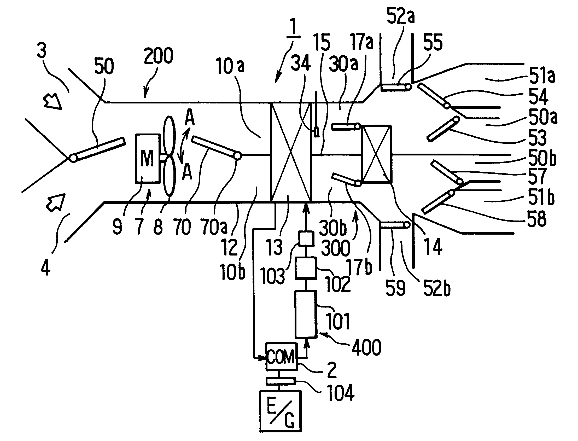
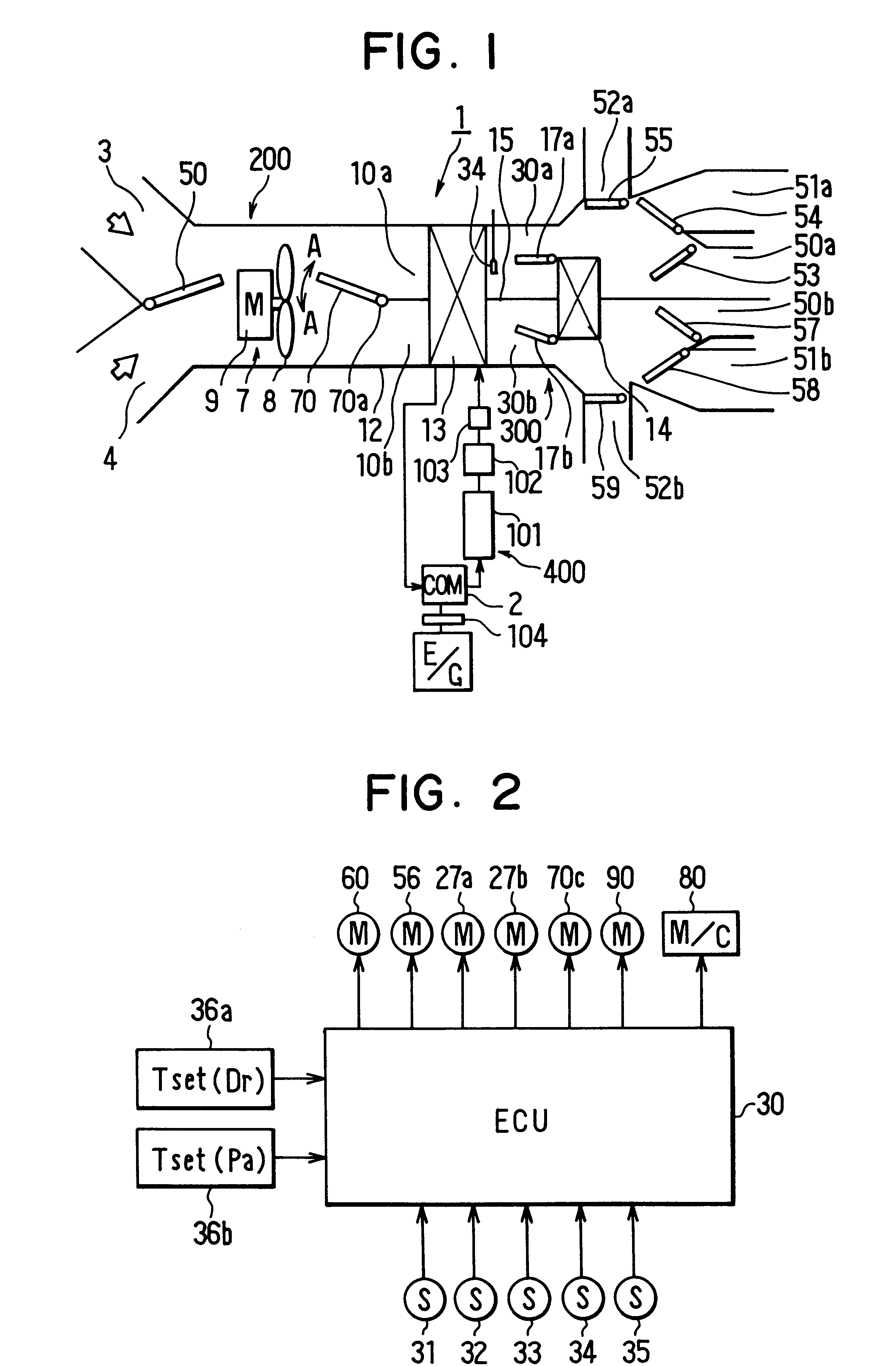
According to a further aspect of the present invention, an air-conditioning system includes a housing having first and second passages through which conditioned air is blown into first and second air-conditioning zones of the passenger compartment, respectively, a cooling heat exchanger disposed in both the first and second passages, a flow control member for controlling a flow rate of air in the first and second passages, a first cooling degree detector disposed in the first passage downstream from the cooling heat exchanger for detecting a first cooling degree of air in the first air passage, a second cooling degree detector disposed in the second passage downstream from the cooling heat exchanger for detecting a second cooling degree of air in the second air passage, and a control unit for controlling air blown into the passenger compartment. The control unit controls the flow control member in such a manner that a difference between an air amount passing through the first air passage and an air amount passing through the second air passage becomes smaller when any one of the first cooling degree and the second cooling degree is lower than a predetermined value. Therefore, when the cooling heat exchanger is possible to be frosted in one of the first and second air passages, temperature of air flowing through the other air passage between the first and second air passages is not greatly increased, thereby preventing the windshield from being fogged (or frosted).
Preferably, the control unit reduces cooling capacity of the cooling heat exchanger when any one of the first cooling degree and the second cooling degree is lower than a predetermined value. Therefore, it can prevent the cooling heat exchanger from being frosted while preventing the windshield from being fogged.
More preferably, the control unit controls the flow control member in such a manner that an air amount passing through an air passage where the cooling heat exchanger is possible to be frosted, between the first and second air passages, is corrected to be increased. Alternatively, an air amount passing through the other air passage, between the first and second air passages, is corrected to be decreased. Thus, it can further prevent the windshield from being fogged.

Problems solved by technology

However, because the conditioned air is blown at the same rate to each side, it is not possible to independently control the air flow rate.
However, providing a separate detector for each passage increases the number of system parts, labor required to assemble the system, and system cost.
On the other hand, in the above-described air-conditioning system, it is difficult to prevent frosting of the evaporator while preventing a windshield from being fogged.

Method used


Image

  • Vehicle-air-conditioning system with cooling degree estimator for left/right temperature control
  • Vehicle-air-conditioning system with cooling degree estimator for left/right temperature control
  • Vehicle-air-conditioning system with cooling degree estimator for left/right temperature control

Examples


Embodiment Construction

)

In the preferred embodiments described above, the invention was applied to a left-right independent control type of air-conditioning unit wherein the inside of the air-conditioner case 12 is partitioned into two passages; however, the invention is not limited to this and can also be applied in the following ways.

For example, in an air-conditioning unit wherein the air-conditioner case is not partitioned into left and right passages and there is only one air-mixing door, a flow control door 70 of the kind described above may be provided, and the flow-distributing door may be controlled so that when solar radiation is entering the right side of the vehicle the flow from outlets on the right side of the vehicle is increased to compensate for the heat generated by the solar radiation.

Further, although in the preferred embodiments described above the temperature of the conditioned air is controlled with air-mixing doors 17a, 17b, each for adjusting the mixture ratio of a cool draft and ...


PUM


Abstract

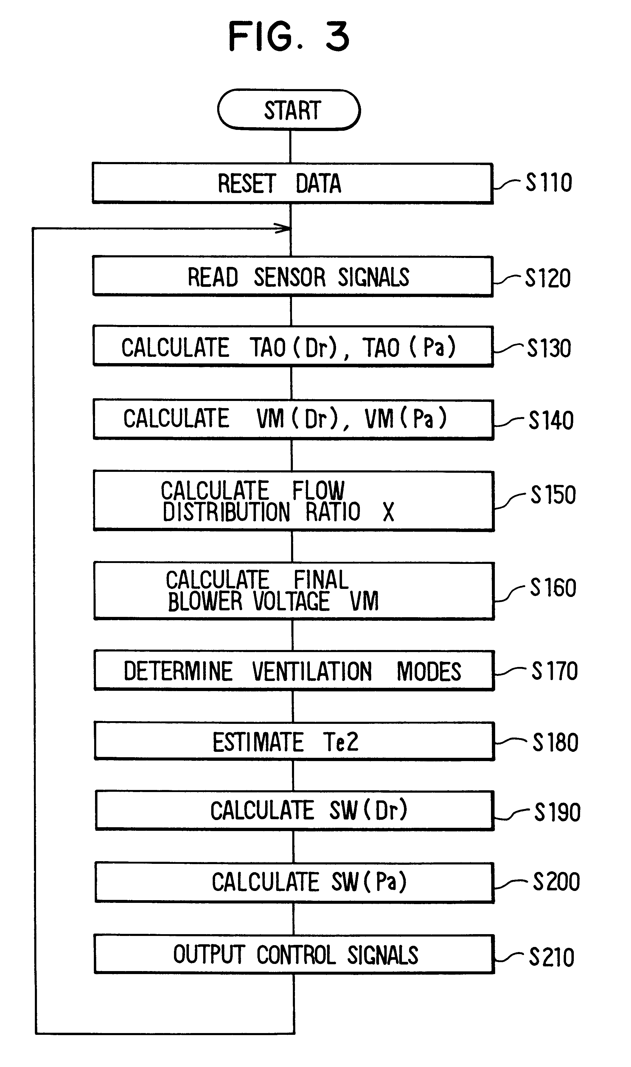
In an air-conditioning system having two air-conditioning passages serving two different air-conditioning zones but having a cooling degree detector provided in only one of the passages to reduce cost, with the degree to which air is cooled in the other passage being estimated based on a cooling degree detected by the detector and the difference between flows of air passing through the passages or an intake temperature of air entering the passages. On the other hand, when an evaporator is possible to be frosted in one of the passages, air flow amount in the one of the passages is corrected to be increased. Therefore, it can prevent a windshield from being fogged while preventing the evaporator from being frosted.

Description

1. Technical FieldThis invention relates generally to vehicle air-conditioning systems wherein air flows in first and second passages can be controlled to different values, and particularly to a reduced-cost system in which a cooling degree detector is provided only in the first passage, and in which the degree of cooling taking place in the second passage is estimated.2. Related ArtAs disclosed in Japanese Unexamined Patent Publication No. Hei. 9-39544, air-conditioning systems wherein the inside of an air-conditioner case is partitioned into two passages to form separate driver seat side and passenger seat side passages are well known. In such a system, an evaporator and a heater core extend across both passages. A driver seat side air-mixing door is provided in the driver seat side passage, and a passenger seat side air-mixing door is provided in the passenger seat side passage so that conditioned air temperatures can be separately matched to the preferences of a driver and a pas...

Claims


Application Information

Patent Timeline
Patent Type & Authority Patents(United States)
IPC IPC(8): B60H1/00
CPCB60H1/00064B60H2001/00135B60H2001/00192
Inventor KAKEHASHI, NOBUHARUOGAWA, YOSHIYUKISAMUKAWA, KATSUHIKO
Owner DENSO CORP
Learn More