
Sample focusing device and method

a focusing device and sample technology, applied in the field of sample focusing devices and methods, can solve the problems of reducing the separation resolution, not the only possible application of field-flow fractionation, and affecting the separation resolution, so as to reduce the separation resolution, avoid sample spreading, and high resolution

Inactive Publication Date: 2001-02-27
FFFRACTIONATION
View PDF13 Cites 26 Cited by
  • Summary
  • Abstract
  • Description
  • Claims
  • Application Information

AI Technical Summary

Benefits of technology

It is desirable to achieve high resolution in separation processes. It is further desirable to inject a narrow pulse sample into a field-flow fractionation or other chromatographic separation apparatus to prevent an increase in sample spread or dilution that reduces the separation resolution. Sample spreading depends in turn on the flow dynamics in the medium where the separation takes place. Consequently, it is also desirable to control the relevant flow dynamics so that sample spreading is avoided.
As illustrated by FIG. 4 and by the operational procedure described above, the invented sample focusing method and device rely on a simplified operation procedure because fewer switching valves are used for the focusing and separation processes. Furthermore, the flow paths used in the focusing stage are more similar to the flow paths used in the separation stage. The operational procedure described in relation to FIG. 4 also helps to explain the improved detection capability of the invented sample focusing method and device. This achievement is partly due to the absence of flow reversal or halting during the transition between the focusing and separation stages of the sample focusing method and device.

Problems solved by technology

Whereas sample species separation according to mass or size is often the goal of field-flow fractionation, this is not the only possible application of field-flow fractionation.
Band broadening is detrimental as it reduces the resolution of separation.
In current practice, the volume of the sample plug is limited by band broadening effects.
The disadvantage of this method is that the carrier flow must be turned on and off; this typically requires a switching valve and extra time for equilibration.
The pressure transient generation is a most detrimental effect because the detectors used in FFF systems are sensitive to pressure transients.
As a consequence of the pressure transient, the detector signal is distorted from its normal baseline value and a significant amount of time may be required for the detector to return to baseline.
Whenever the detector response is disturbed, the separation cannot be accurately monitored, especially for species that elute at the beginning of the separation stage.
Additionally, the pressure transient may broaden or otherwise disturb the sample zone which is precisely positioned in its equilibrium distribution during the previous stop-flow period.
Either of these reasons will cause poor separation resolution.
In addition to these undesired pressure pulses, a stop-flow process may also lead to another undesirable effect, which is adhesion of sample species at the accumulation wall.
Second, engineering the pinched inlet may present difficulties because high performance FFF channels are already very thin, typically 100-200 micrometers.
Because of this small dimension, reducing the channel thickness near the inlet is difficult.
Manufacturing a channel with an even channel thickness of just a few micrometers in the pinched inlet area is difficult.
Fourth, at high channel flow rates, eddy currents may be generated at the interface between the pinched inlet area and the full channel thickness.
Such eddy currents are undesirable because they may disturb the distribution of sample next to the accumulation wall.
Finally, the reduced thickness of the channel at the inlet is susceptible to clogging.
Nevertheless, this method has some disadvantages.
Another disadvantage, common to the pinched channel inlet system, is that the sample has an increased opportunity for band broadening relative to the stop-flow method.
This feature reduces the opportunity for sample adsorption on the accumulation wall.
Furthermore, the pinched inlet and the hydrodynamic relaxation methods require a sufficiently short sample injection time to avoid sample diffusion during injection.
Sample diffusion would otherwise form an undesirable and effectively larger sample plug.
Neither the pinched inlet nor the hydrodynamic relaxation method, however, provide complete sample relaxation.
Unfortunately, the stop flow method is more time consuming than stopless flow injection, it is more conducive to particle adhesion to the accumulation wall, and it typically produces a false signal due to the pressure pulses that are induced by abrupt flow changes in the channel.
The disadvantage of the outlet flow sample focusing method lies in the transition that must be made between focusing and separation.
This requires a complex arrangement of pumps, tubing, and valves.
Thus, there is a period of unstable flow during the transition period.
A consequence of this flow instability is that the focused sample is disturbed during the period of unstable flow; furthermore, the focused sample is also disturbed by the pressure transient.
However, this requires extra valves and a pressure transient is generated due to the action of the valve.
The purpose of this mechanical device is to inject a sample at a high pressure into a chromatographic column, but it does not focus the injected sample.

Method used


Image

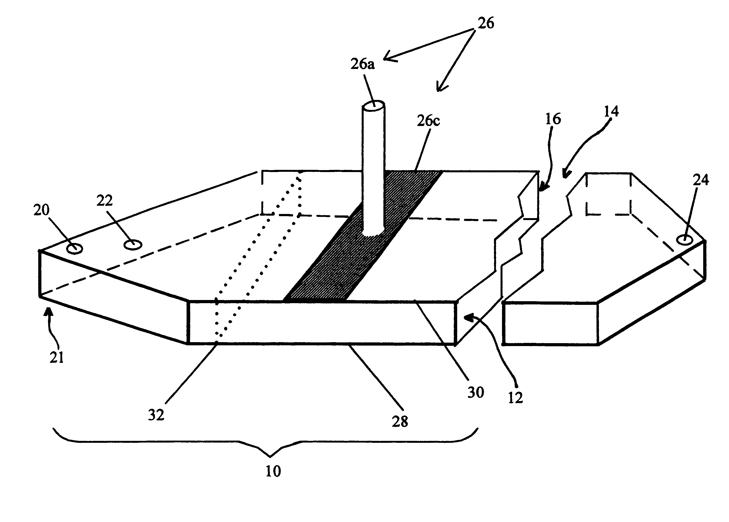
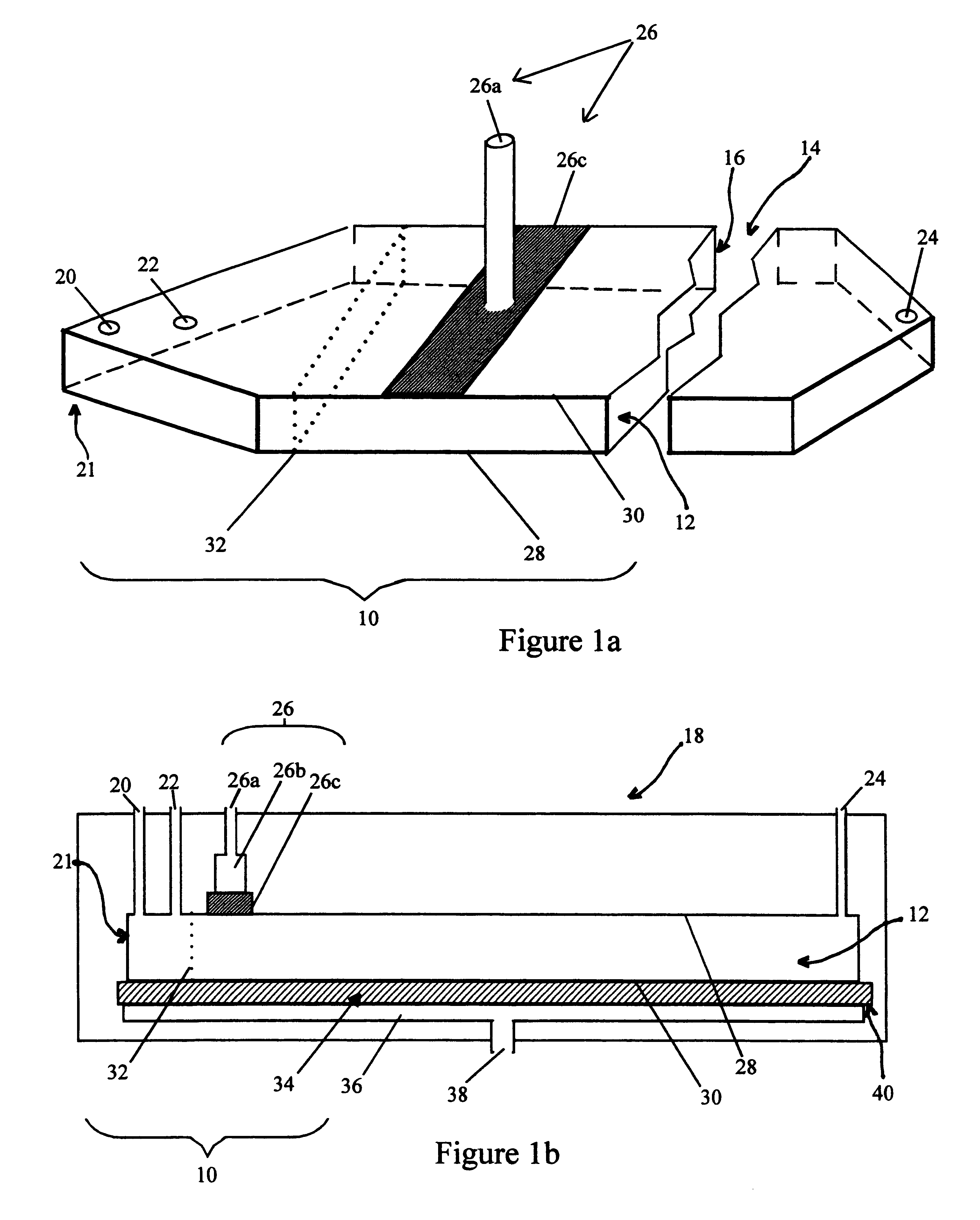
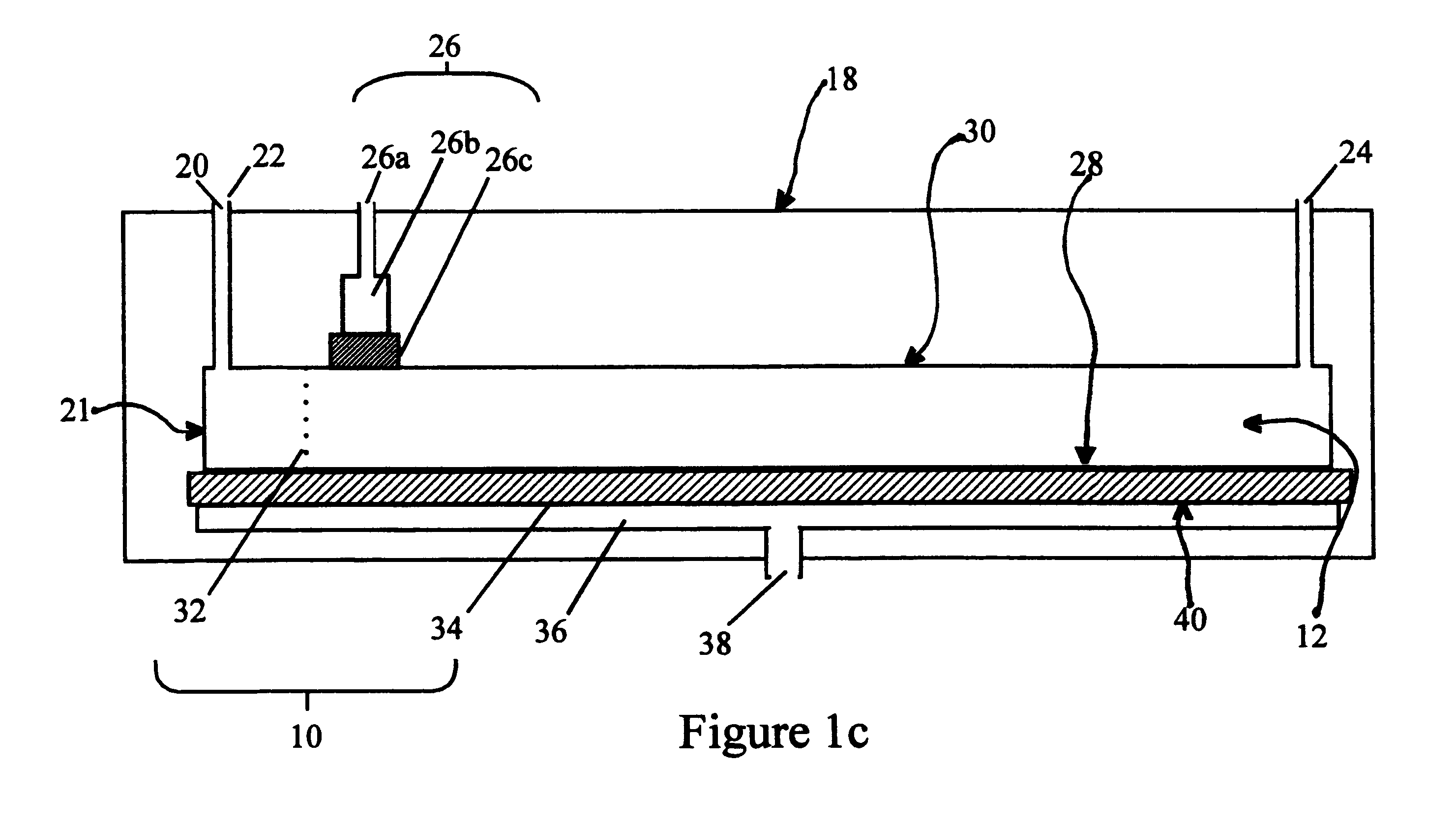
  • Sample focusing device and method
  • Sample focusing device and method
  • Sample focusing device and method

Examples


Embodiment Construction

The sample focusing device and method of this invention were tested using a refractive index detector as the detection system. This type of detector is especially sensitive to pressure transients and so its response should indicate the presence and magnitude of a pressure transient. The specific refractive index detector used, the Optilab model DSP (Wyatt Technology Corp., Santa Barbara, Calif.), uses interferometry to detect refractive index changes.

For comparison purposes, an asymmetrical flow FFF channel was set up under outlet focusing method conditions. FIGS. 5a and 5b show diagrams of this instrumental set up. The flow lines and positions of the switching valves are shown for the focusing stage according to the outlet focusing method in FIG. 5a; the valve positions and flow lines for the separation stage according to the same method are shown in FIG. 5b. The experimental conditions for the focusing stage were those given in Table 2

The flow rates during the separation phase wer...


PUM

PropertyMeasurementUnit
diameteraaaaaaaaaa
total volumeaaaaaaaaaa
thicknessaaaaaaaaaa

Abstract

Sample focusing method and device for field-flow fractionation techniques that lead to improved detection, improved separation resolution, and a compressed sample plug while permitting a more straightforward quantitation of peaks and reliable large volume injections. The method and device can be implemented in separations that are performed by a variety of field-flow fractionation techniques, including thermal FFF, electrical FFF, sedimentation FFF, gravitational FFF, dielectric FFF, photophoretic FFF, flow FFF, asymmetric flow FFF, and symmetric flow FFF. The sample focusing device can be integrally built into a separation channel or it can be manufactured as an attachable independent piece.

Description

1. The Field of the InventionThe present invention relates generally to analytical separation techniques such as field-flow fractionation. More specifically, the present invention relates to a method and a device for introducing samples in analytical separation apparatuses, and in particular to field-flow fractionation systems.2. Related ApplicationThis is a division of application Ser. No. 09 / 032,188, filed Feb. 27, 1998, on behalf of Yong Jiang, Ph.D., Marcia Elaine Hansen, Ph.D., Michael Eliot Miller, Ph.D., and Andreas Martin Kummerow, entitled Sample Focusing Device and Method, which is hereby incorporated herein by reference.3. Present State of the ArtField-flow fractionation is a separation and characterization technique that relies on the effects of an applied field on a sample that is carried by a fluid flow. This fluid flow moves down a channel that will hereinafter be referred to as the "channel". The stream flowing along the channel will be referred to by the term "chann...

Claims


Application Information

Patent Timeline
Patent Type & Authority Patents(United States)
IPC IPC(8): B03B5/00G01N30/00
CPCB03B5/00G01N30/0005
Inventor JIANG, YONGHANSEN, MARCIA E.MILLER, MICHAEL E.KUMMEROW, ANDREAS M.
Owner FFFRACTIONATION
Learn More