
Computer system with storage device mapping input/output processor

Inactive Publication Date: 2001-02-27
ORACLE INT CORP
View PDF14 Cites 197 Cited by
  • Summary
  • Abstract
  • Description
  • Claims
  • Application Information

AI Technical Summary

Benefits of technology

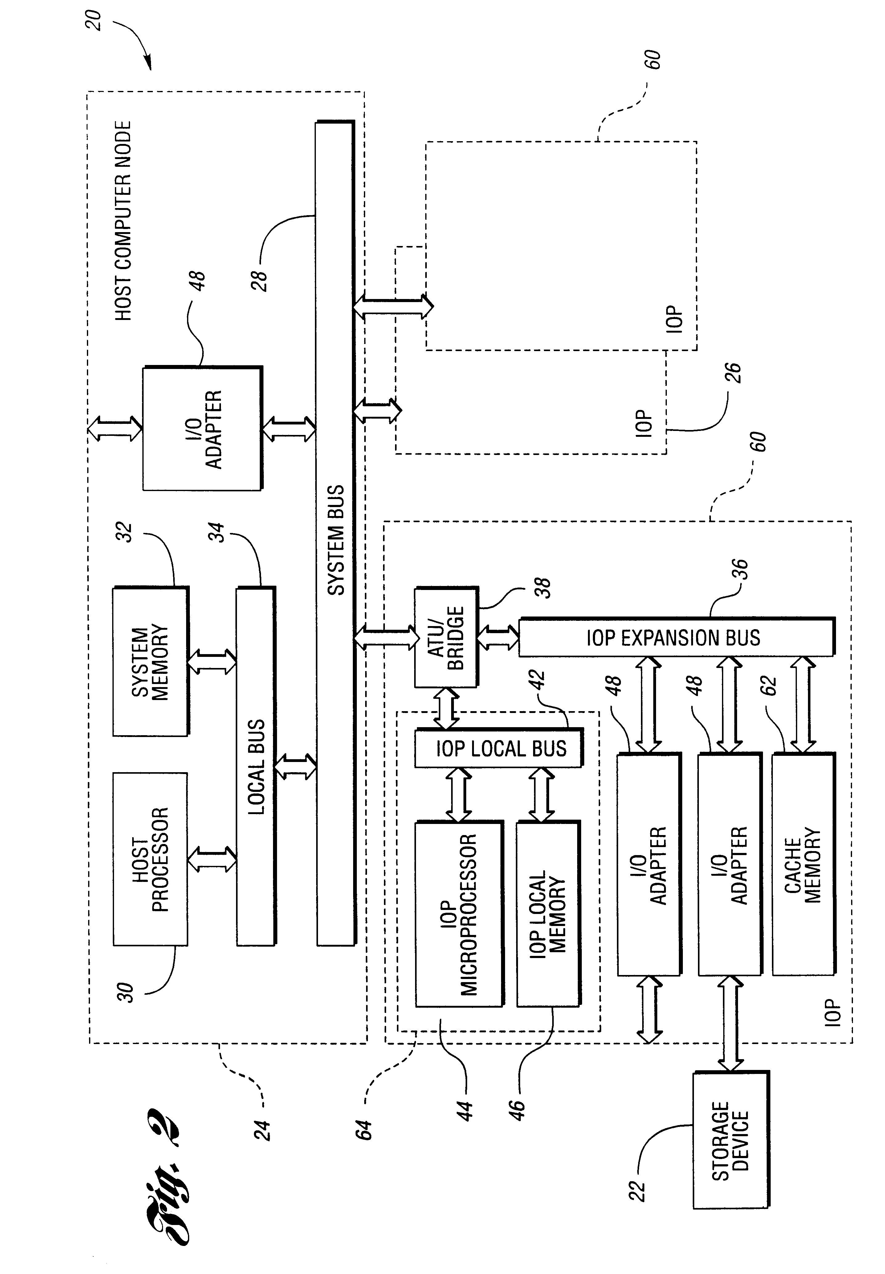
In yet another embodiment, a high speed IO adapter is connected to another high-speed IO adapter in at least one other IOP. The control logic transfers data between the cache memory and a corresponding cache memory in the other IOPs, thereby implementing a global cache memory.
In still another embodiment, the IOP is co

Problems solved by technology

The nature of this scheme imposes certain limitations upon IO operations.
First, the capacity of system memory available specifically for IO operations at any given time is limited.
Third, the resulting associated performance degradation may limit the number and data rates of storage devices serviced.
First, data transfer operations into and out of the IOP local memory consume a notable amount of bandwidth of the IOP local bus connecting the IOP processor to local memory.
Second, use of IOP local memory as a repository for data involved in an IO operation is subject to the same various resource allocation issues and constraints found when system memory is used.
Both in-board and out-board device virtualization have undesirable properties.
Out-board device virtualization generally requires complex and expensive storage devices.

Method used


Image

  • Computer system with storage device mapping input/output processor
  • Computer system with storage device mapping input/output processor
  • Computer system with storage device mapping input/output processor

Examples


Embodiment Construction

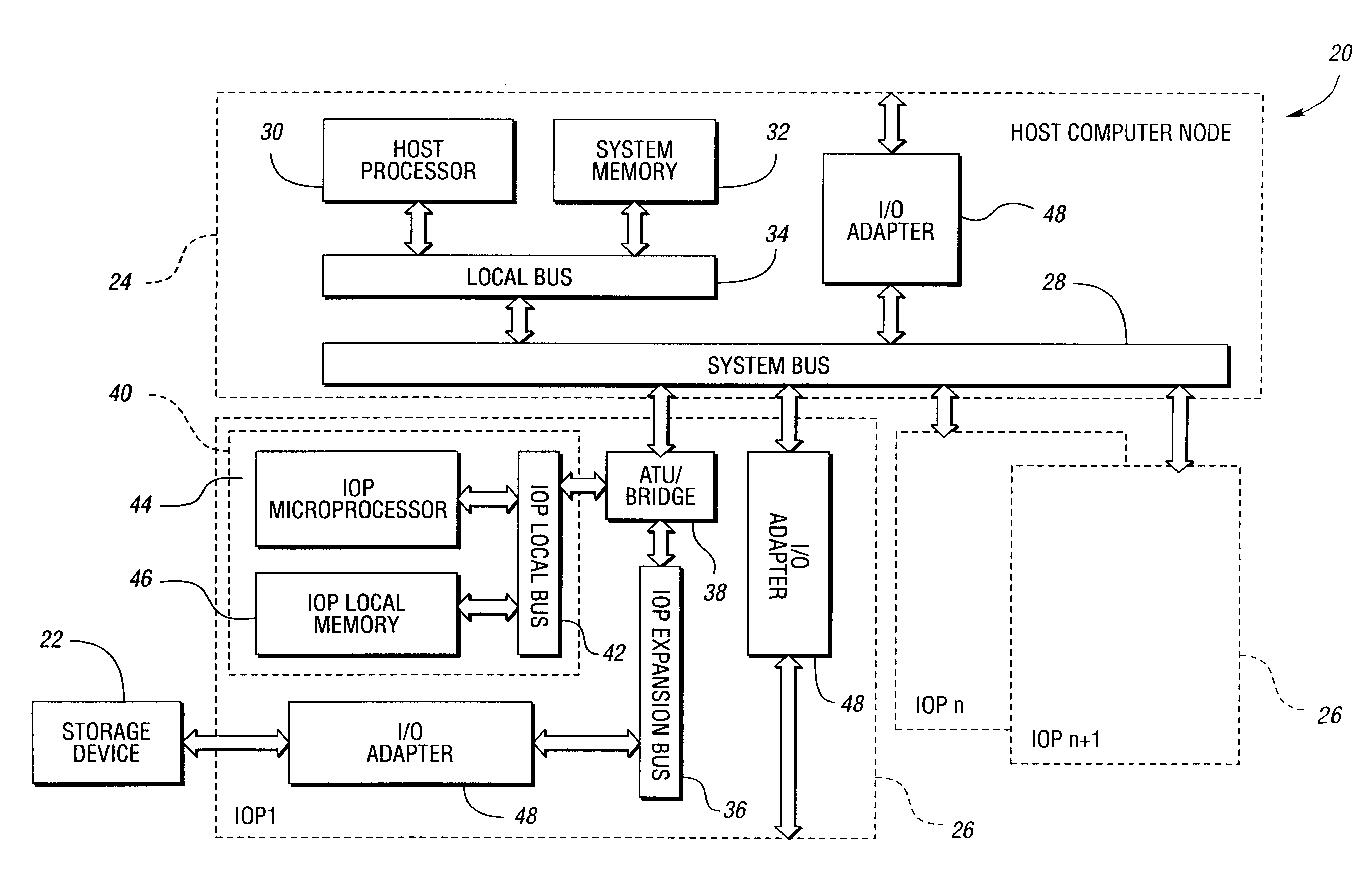
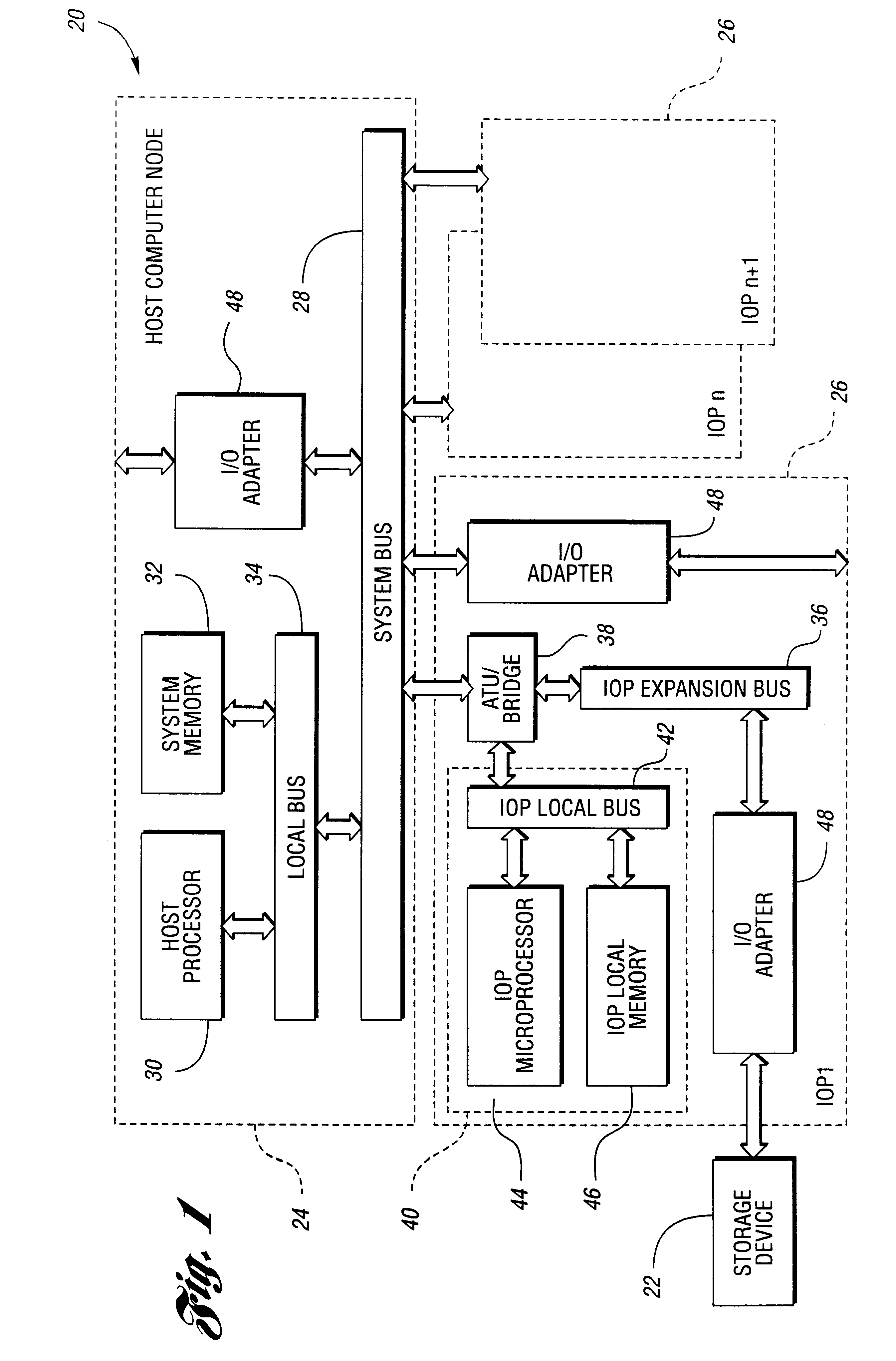
Referring now to FIG. 1, a block diagram of a prior computer system is shown. A computer system, shown generally by 20, can access one or more storage devices 22. Computer system 20 includes host computer node 24 and at least one input / output processor (IOP) 26. Host computer node 24 includes system bus 28, at least one host processor 30 connected to system bus 28, and system memory 32 connected to system bus 28. Often, local bus 34 allows host processor 30 to access system memory 32 without having to use system bus 28. In such architectures, local bus 34 provides access to system bus 28 for host processor 30 and system memory 32.

IOP 26 includes IOP expansion bus 36 connecting IOP 26 with system bus 28. IOP expansion bus 36 may include bridge 38. Bridge 38 includes driver electronics and may function as an address translation unit (ATU). IOP 26 also includes control logic 40 connected to expansion bus 36. Control logic 40 includes local bus 42 connected to expansion bus 36, IOP micr...


PUM


Abstract

An input / output processor provides device virtualization "on-board" through the use of a dedicated IO cache memory. A computer system includes at least one host processor and associated main memory each with access to a system bus. Each input / output processor is also connected to the system bus through an expansion bus. IO adapters within the input / output processor each connect at least one storage device to the expansion bus. Also connected to the expansion bus is the cache memory and a control logic. The control logic receives a data transfer request from a requesting host processor. The data transfer request is mapped to a cache device object. The cache device object has associated data maintained in the cache memory. If any storage device is required for the data transfer, the data transfer request is mapped to the storage device capable of servicing the request. A location in cache memory is determined based on the mapped cache device object. The data transfer is performed based on the location and, if needed, the determined storage devices. This provides the host computer with a virtual view of the storage devices.

Description

The present invention relates to input / output processors permitting input / output device virtualization.Computer systems span a variety of architectural designs. Many of these designs have several general features in common. One or more host processors, such as a microprocessor, are connected via a local bus to system memory. The system memory is used to provide the connected processors with program instructions and associated software program data. These programs include at least one operating system and a plurality of application programs.To transfer data to and from an external storage device, such as a disk or tape drive, an input / output (IO) adapter is normally used. These IO adapters are physically connected to a system bus. The system bus provides a common standardized interface between IO adapters connected to the same bus. The system bus is connected to the local bus so that data can be transferred between the IO adapters and software programs executing upon the host process...

Claims


Application Information

Patent Timeline
IPC IPC(8): G06F12/08
CPCG06F12/0875
Inventor WEST, THOMAS D.
Owner ORACLE INT CORP
Learn More