Pipe stand instrument heater and mounting system

a technology for instruments and enclosures, applied in steam boiler components, valve details, speed/acceleration/shock instruments, etc., can solve the problems of mounting heaters within enclosures that can burn or injure people performing maintenance or adjusting instruments, and the heat loss is increased

Inactive Publication Date: 2001-03-06
INTERTEC INSTR
View PDF20 Cites 28 Cited by
  • Summary
  • Abstract
  • Description
  • Claims
  • Application Information

AI Technical Summary

Problems solved by technology

Prior art heaters take up additional valuable space around the instrument, necessitate careful engineering to ensure fit, and require larger instrument/manifold/enclosures which necessarily re

Method used


Image

  • Pipe stand instrument heater and mounting system
  • Pipe stand instrument heater and mounting system
  • Pipe stand instrument heater and mounting system

Examples


Embodiment Construction

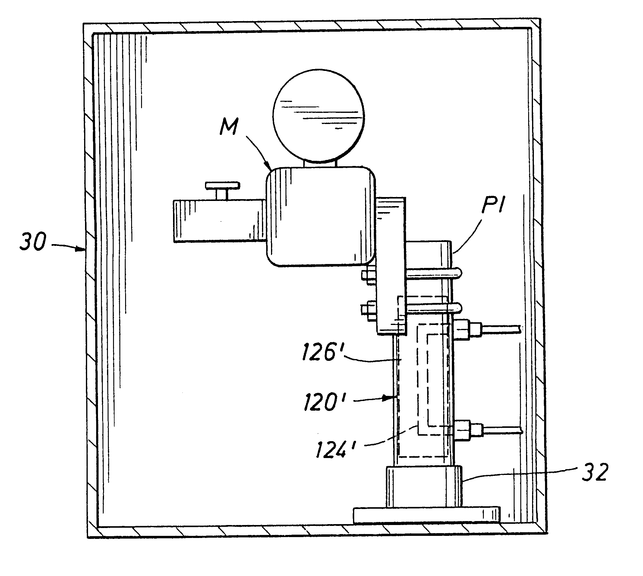
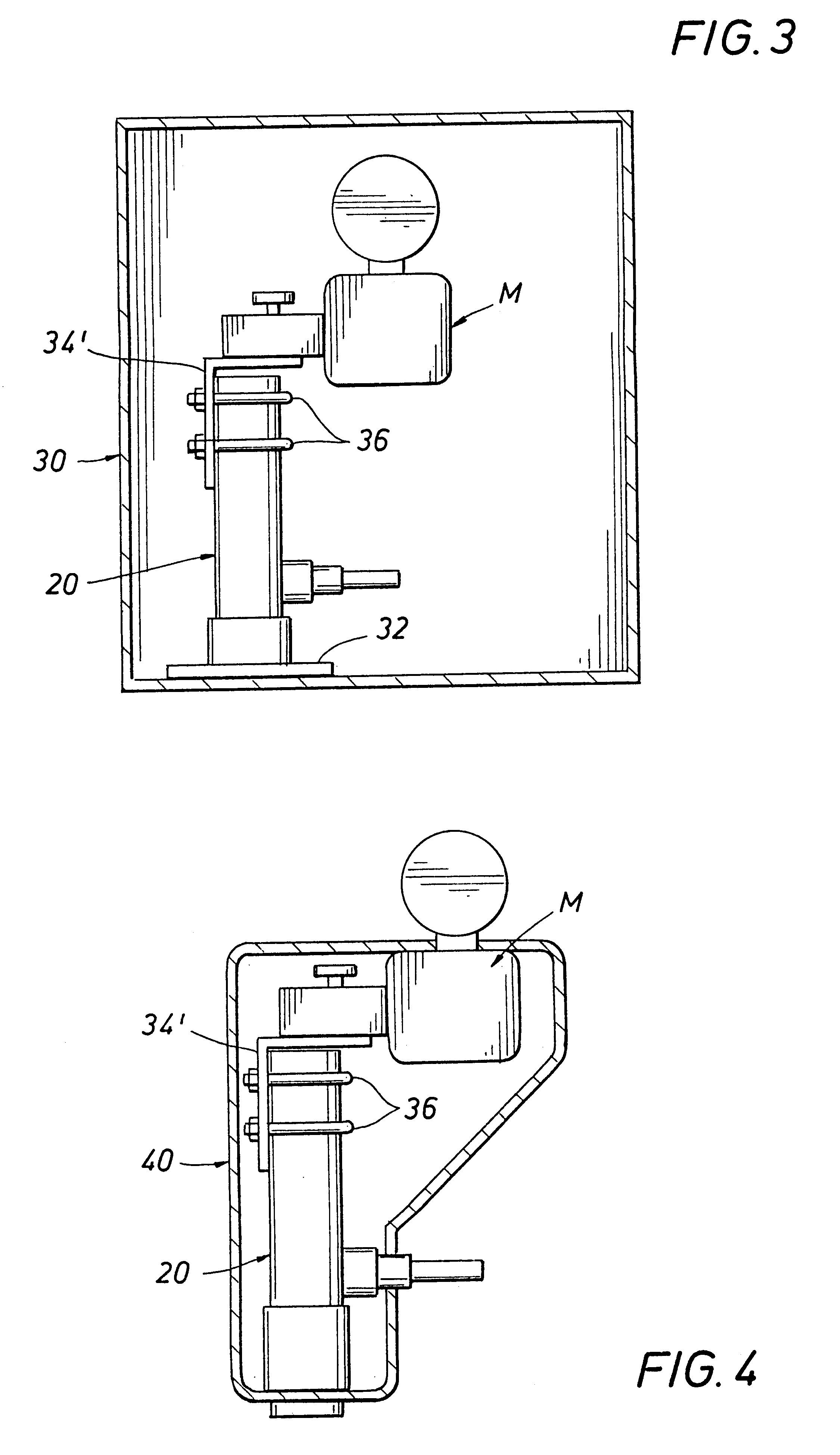
In the prior art, a hard case enclosure for mounting instruments within included a 2" mounting post, typically extending vertically from the bottom of the hard case enclosure. The instrument or manifold was typically mounted to the mounting post with U-bolts. The prior art instrument heater was mounted to the instrument or manifold, walls of the enclosure or to the exterior of the mounting post.

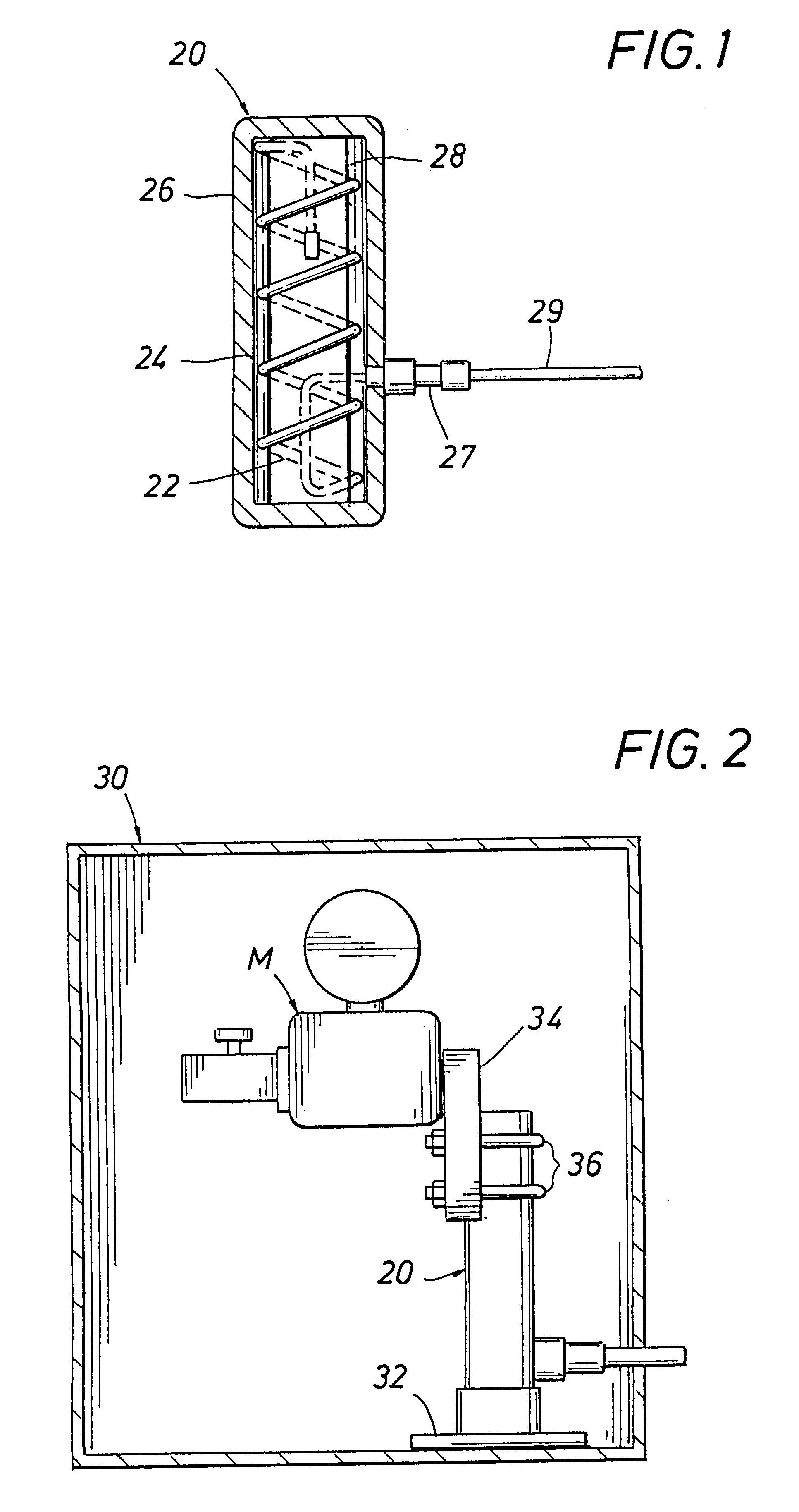
The pipe stand instrument heater according to a first embodiment of the present invention, generally designated as 20, is shown in FIG. 1. The pipe stand instrument heater 20 includes a core 22 comprising a spiraled coil installation of a self-regulating heater cable 24 within a pipe housing 26, preferably cylindrical in shape and having closed ends. Preferably, the pipe housing 26 is made from 2" Nominal Pipe Size ("NPS") or a casting the same size as 2" NPS. The self-regulating heater cable 24 preferably includes a high temperature conductive polymer based cable. One type of suitable conduc...


PUM

PropertyMeasurementUnit
Diameteraaaaaaaaaa
Flow rateaaaaaaaaaa
Diameteraaaaaaaaaa

Abstract

A pipe stand instrument heater system heats an instrument within an enclosure supported by a pipe stand. The heater system includes a housing mounted to the pipe stand and a heater unit in the housing. A bracket is provided for mounting the instrument to the housing. The heater unit can be powered by electric, steam or other fluids.

Description

1. Field of the InventionThe present invention relates generally to instrument heaters, and more particularly relates to instrument heaters for pipe stand-mounted industrial instruments.2. Description of the Related ArtCommonly, industrial instruments are mounted to a pipe stand having a diameter of approximately two inches. The instruments are generally mounted to the pipe stand with a pair of U-bolts. In many environments it is necessary to provide a heated enclosure for the instruments. Two categories of enclosures are typically used. The first type is a hard case or box-like structure which is usually hinged or provided with quick release latches to access the instrument contained within the hard case. The second type of enclosure is a soft flexible case that is fitted around the instrument.Typically, in the past an instrument heater was mounted in close proximity to the instrument and the enclosure necessarily was required to have enough inside space to accommodate both the hea...

Claims


Application Information

Patent Timeline
IPC IPC(8): H05B3/00H05B3/10H05B3/06F22B37/02F27D11/02F28D15/02H05B3/62
CPCH05B3/00H05B3/10Y10T137/6579Y10T137/6606
Inventor CAMPBELL, BRYAN J.BARTH, ROY E.HUFF, W. GREGORYZABOROWSKI, RONALD W.BONORDEN, CHARLES M.SCHLAMEUS, DAVID L.
Owner INTERTEC INSTR
Why Eureka
Try Eureka