This process has extensive costs associated with it.
It takes big equipment and lots of power to lift to surface the large amounts of fluid required to retrieve a small proportion of oil.
There are then costs associated with separating the oil from the water at surface, handling the then pure (i.e. no oil), but still possibly corrosive water, and disposing of it in a dedicated disposal well or by other means.
However, a large proportion of the world's producing oil wells do not flow on their own and some form of
artificial lift is required.
Unfortunately, many producing
petroleum wells do not have an acceptable disposal zone below the production zone but do have one above the production zone.
Again however, although not specifically stated, this process must be directed at gas wells and flowing oil wells as there is no provision for artificially lifting fluids to surface.
The additional challenge however, is to artificially lift the desired hydrocarbons to surface, while disposing of the water to a zone in the same wellbore.
Although incredibly simple and effective there are some inherent disadvantages to using a PCP in this application.
Historically, PCP's have had specific limitations over other common forms of
oil well artificial lift (i.e. reciprocating sucker rod pumps and electric submersible pumps).
Firstly, because of the required use of an
elastomer stator, the serviceability in a pure water application and / or in light oils containing aromatics is severely restricted.
Secondly, PCP's have limited pressure capabilities which
restrict their use in deeper wells and more specifically, in a separation / disposal application,
restrict their use in wells where the disposal zone might have a high
reservoir pressure or low
infectivity.
Thirdly, to get the fluid to warrant the inherently high service and repair costs, most PCP are still in a "tubing pump" configuration.
That is, the entire pump needs to be run and retrieved on tubing, which to someone familiar in the art, will understand is a distinct
disadvantage when compared to a reciprocating sucker rod pump, the embodiment of the current invention, which can be run and retrieved with the sucker rod string alone and does not require the "pulling" of both the rods and then the tubing.
However, the DAP does have some distinct disadvantages of its own.
Secondly, the DAP as described in the patent requires the use of several conventional ball and seat valving systems that are attached external to the regular smooth profile of the "tubing pump".
A person familiar in the art will understand that this will severely reduce the ruggedness of any downhole tool.
This condition could easily result in actual physical damage when running or retrieving the
system.
Thirdly, and most importantly, the DAP injects the disposal water on the downstroke.
Again, a person familiar in the art will understand that, with an opposing upward force on the downstroke, the sucker rods in the well bore will tend to buckle, reducing bottom hole pump
stroke and leading to a myriad of other potential mechanical problems in the production system.
Although special sucker rod string design can effectively overcome small upward forces on the downstroke, the solutions will become impractical at higher disposal zone reservoir pressures and low permeabilities.
Finally, the DAP patent does not suggest that the system can be utilized with an above production disposal zone.
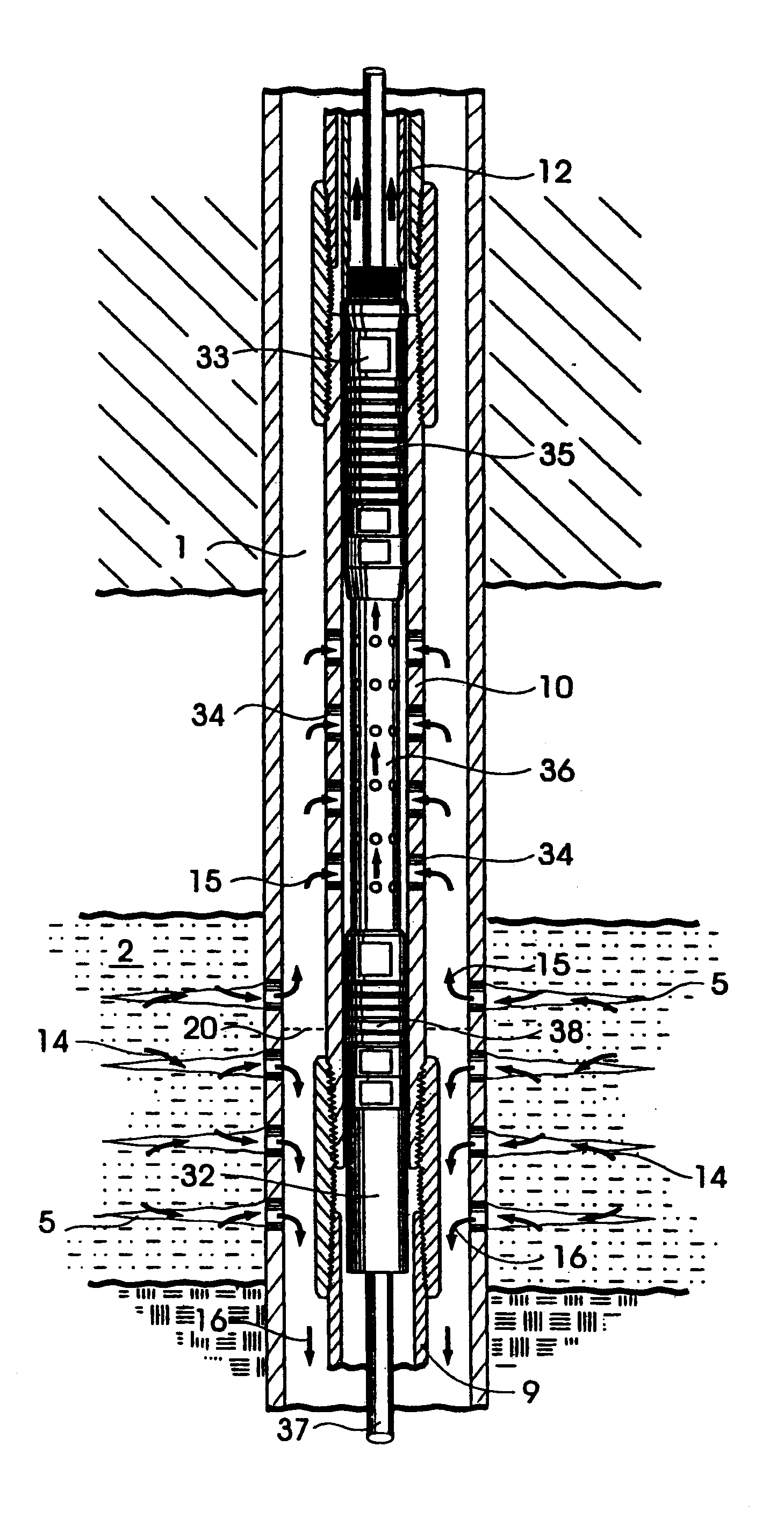
There are no protuberances on the outside of the system to cause difficulties during wellsite operations.

