X-ray diagnostic system preferable to two dimensional x-ray detection

a diagnostic system and x-ray technology, applied in the field of x-ray diagnostic systems, can solve the problems of large exposure of patients, artifacts on tomograms, troublesome handling,

Inactive Publication Date: 2001-03-06
KK TOSHIBA
View PDF4 Cites 395 Cited by
  • Summary
  • Abstract
  • Description
  • Claims
  • Application Information

AI Technical Summary

Problems solved by technology

This requires troublesome handling for exchange of the X-ray films, while exposure of patients becomes large.
Thus, as the number of set slices increases, variance in the breath hold becomes larger, being likely to cause phase shifts resulting in artifacts on tomograms.
However, the above analog- and digital-type X-ray tomosynthesis systems still have some shortcomings which have not been unsolved.
First, control for moving the X-ray tube and the detector in synchronized timing is extremely difficult in terms of technical aspects.
Higher accuracy synchronization control requires more complex control mechanisms and control circuits, resulting in an increase in manufacturing costs.
Second, there is a problem of positional shifts of the X-ray tube (i.e., X-ray focus).
Since the conventional tomosynthesis systems do not have particular countermeasures in this respect, such positional shifts surely causes artifacts, deteriorating image quality.
Third, there is a problem concerning movement loci made by the X-ray tube.
The conventional systems do not take account of any special countermeasure, image artifacts arisen due to such movement loci may reach to unnegligible levels.
The fourth problem is about contrast resolutions.
The prior digital type systems, which do not employ any particular prevention of this influence, also suffer from the same drawback.
The fifth problem concerns enlargement ratios of images.
The conventional tomosynthesis system cannot produce tomograms in which the image enlargement ratio is taken i

Method used


Image

  • X-ray diagnostic system preferable to two dimensional x-ray detection
  • X-ray diagnostic system preferable to two dimensional x-ray detection
  • X-ray diagnostic system preferable to two dimensional x-ray detection

Examples


first embodiment

First, features (functions and constructions) applicable to an X-ray tomosynthesis system according to the present invention will now be listed every category, and a first embodiment covering them all will then be explained. The X-ray tomosynthesis system can be constructed such that it is able to operate based on an arbitrary selected one feature or a plurality of arbitrary selected features.

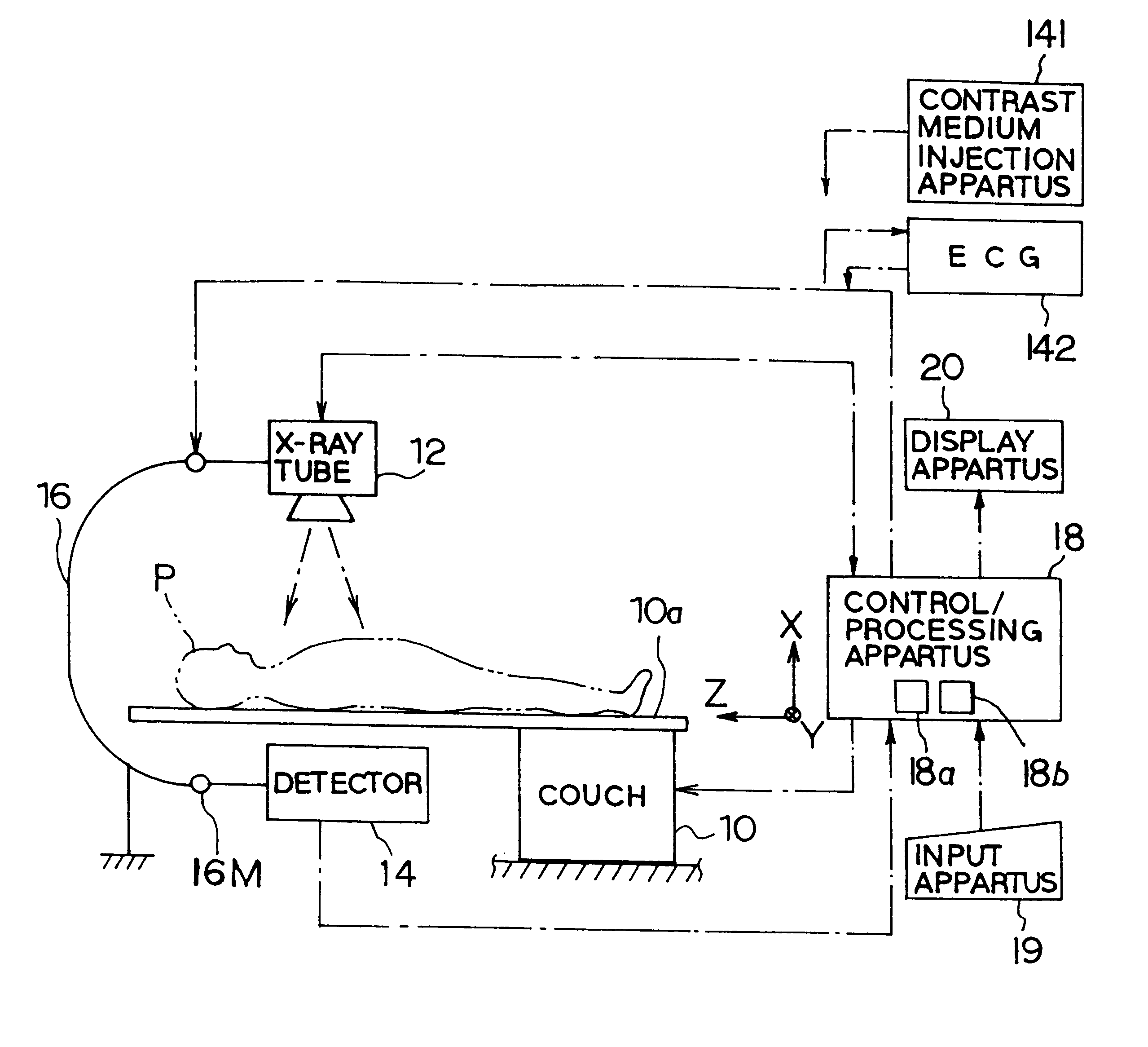
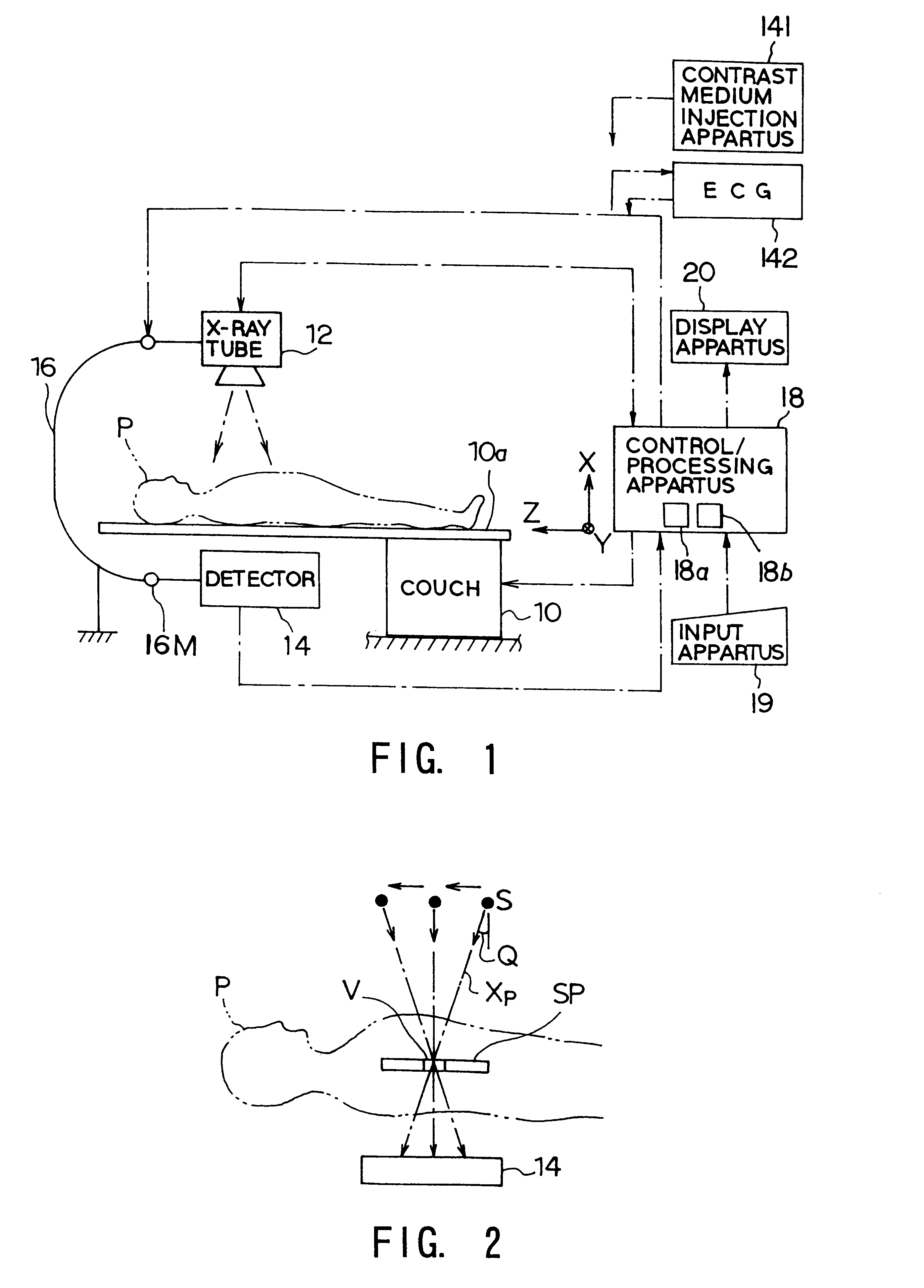
The overall schematic construction of the X-ray tomosynthesis system is shown in FIG. 1.

The X-ray tomosynthesis system comprises a patient couch 10, X-ray tube 12, X-ray detector 14, supporting member 16, and control / processing apparatus 18. An input apparatus 19 and a display apparatus 20 are coupled with the control / processing apparatus 18.

The couch 10 has a tabletop 10a slidable in its longitudinal direction. On the tabletop 10a, a patient (subject to be imaged) is laid, normally, on one's back, for imaging. The X-ray tube 12 and X-ray detector 14 are arranged by the supporting member 16 so ...

second embodiment

A second embodiment of the present invention will now be described in conjunction with FIGS. 63 to 66. This embodiment is practiced into an X-ray tomosynthesis system in which the movement of the tube and the detector is simplified for an easy image recombination.

An X-ray tomosynthesis system shown in FIG. 63 is constructed such that the detector and a subject is fixedly placed in position and only the tube is allowed to move. More specifically, the X-ray detector 14 is formed into a large-size, direct-conversion, digital-type detector, and placed under the tabletop 10a, forming the detector under-arranged system. The term "large-size" used herein means a two-dimensional size which is capable of receiving all the transmitted X-rays in a plurality of views in a state that the detector are positionally fixed and the X-ray tube 12 is moved.

The X-ray detector 14 acquires projection data at intervals (for example, 100 times / sec.) and outputs them through a memory 120 to a CPU 122 serving...

third embodiment

A third embodiment of the present invention will now be described in conjunction with FIGS. 68 to 81A and 81B, an X-ray imaging system of the present invention is practiced into a single plane type of X-ray diagnostic system. Although this system has a total of five imaging modes consisting of "fluoroscopic / radiographic mode", "subtraction imaging mode", "tomographic mode", "reconstruction mode (without subtraction)", and "reconstruction mode of subtraction images", the system constructions of all the modes becomes too complicated to understand them when they are packed together in one drawing. Therefore, for the sake of an easy of understanding, the constructions for each imaging mode is separately depicted from FIGS. 68 to 71.

Construction Corresponding to Fluoroscopic / radiographic Mode

As for the construction corresponding to the fluoroscopic / radiographic mode, the X-ray diagnostic system comprises, as shown in FIGS. 68, 80A and 80B, has a couch 201, an X-ray generator 202, planar-...


PUM


Abstract

An X-ray tomosynthesis system as an X-ray diagnostic system is provided. The system comprises an X-ray generator irradiating an X-ray toward a subject, and a planar-type X-ray detector detecting the X-ray passing through the subject and outputting two dimensional imaging signals based on the detected X-ray. The system comprises a supporting/moving mechanism supporting at least one of the X-ray generator and the X-ray detector so that the at least one is moved relatively to the subject. The system also comprises an element setting a ROI position of the subject, an element for obtaining a plurality of three dimensional coordinates of pixels included in the ROI, a calculating element obtaining two dimensional coordinates of data in the two dimensional imaging signals for each of the two dimensional imaging signals detected by the X-ray detector, the data being necessary for obtaining pixel values of the three dimensional coordinates; and an element for obtaining the pixel value of each of the three dimensional coordinates by extracting the corresponding data of the two dimensional coordinates from the detected two dimensional imaging signals and adding the extracting data.

Description

1. Field of the InventionThe present invention relates to an X-ray diagnostic system, preferably to a system having a two dimensional X-ray detector, in particular, to the system which is capable of producing a tomogram at any slice only by adding projection data of a plurality of frames acquired by multiple exposures of X-rays to a subject, and the system which is capable of not only altering an X-ray incidence angle on the detector for multiple-purpose imaging but also performing imaging at arbitrary enlargement ratios using the two dimensional X-ray detector.2. Discussion of the BackgroundAt present, such modalities as an X-CT scanner, X-ray tomosynthesis system, magnetic resonance imaging (MRI) system, and diagnostic ultrasound apparatus have been clinically used for acquiring tomographic images of patients.Of these X-ray tomosynthesis systems were temporarily used in the past because of relatively easier acquisition of tomograms, but advance in X-ray CT scanners and MRI systems...

Claims


Application Information

Patent Timeline
IPC IPC(8): A61B6/00G03B42/02A61B6/03H04N5/225G01N23/04A61B6/02G16H10/60
CPCA61B6/00A61B6/032A61B6/4233A61B6/469A61B6/481A61B6/504G03B42/02A61B6/4291A61B6/4092A61B6/4085A61B6/541A61B6/4021
Inventor NAMBU, KYOJIROTAGUCHI, KATSUYUKIOISHI, SATORU
Owner KK TOSHIBA
Why Eureka
Try Eureka