
Method and apparatus for shaping a site for anchoring an implant and to provide bone augementation and shape conformity

Inactive Publication Date: 2001-03-13
REGNI JR GERALD J
View PDF7 Cites 36 Cited by
  • Summary
  • Abstract
  • Description
  • Claims
  • Application Information

AI Technical Summary

Benefits of technology

Another object of the present invention is to provide a novel tool for preparing a site for an implant having the capability of compressing bone within the cavity of the site to provide a more uniform socket for receipt of an implant which significantly enhances the precision placement of the implant or existing size or a scan and cut of a prosthetic component to fit on site.

Problems solved by technology

1. the competency of the doctor (implantologist or prosthodontist);
2. the availability of bone and the proper configuration thereof;
3. the patient's immunological system and habits that may contribute to accelerated breakdown;
4. the compliance of the patient including the immune system function which will be handled holistically.
5. non-predictable bone augmentation procedures.

Method used


Image

  • Method and apparatus for shaping a site for anchoring an implant and to provide bone augementation and shape conformity
  • Method and apparatus for shaping a site for anchoring an implant and to provide bone augementation and shape conformity
  • Method and apparatus for shaping a site for anchoring an implant and to provide bone augementation and shape conformity

Examples


Embodiment Construction

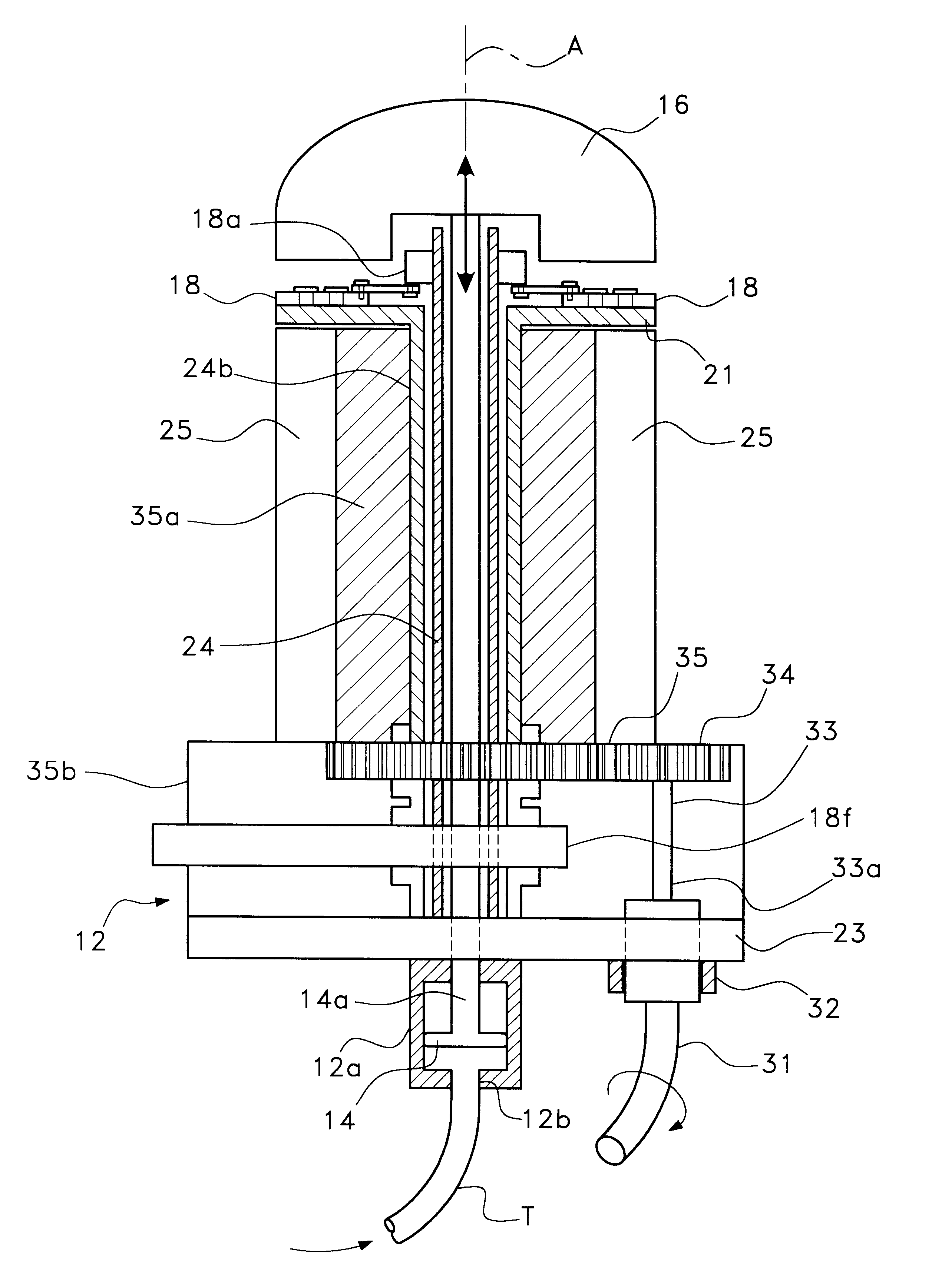
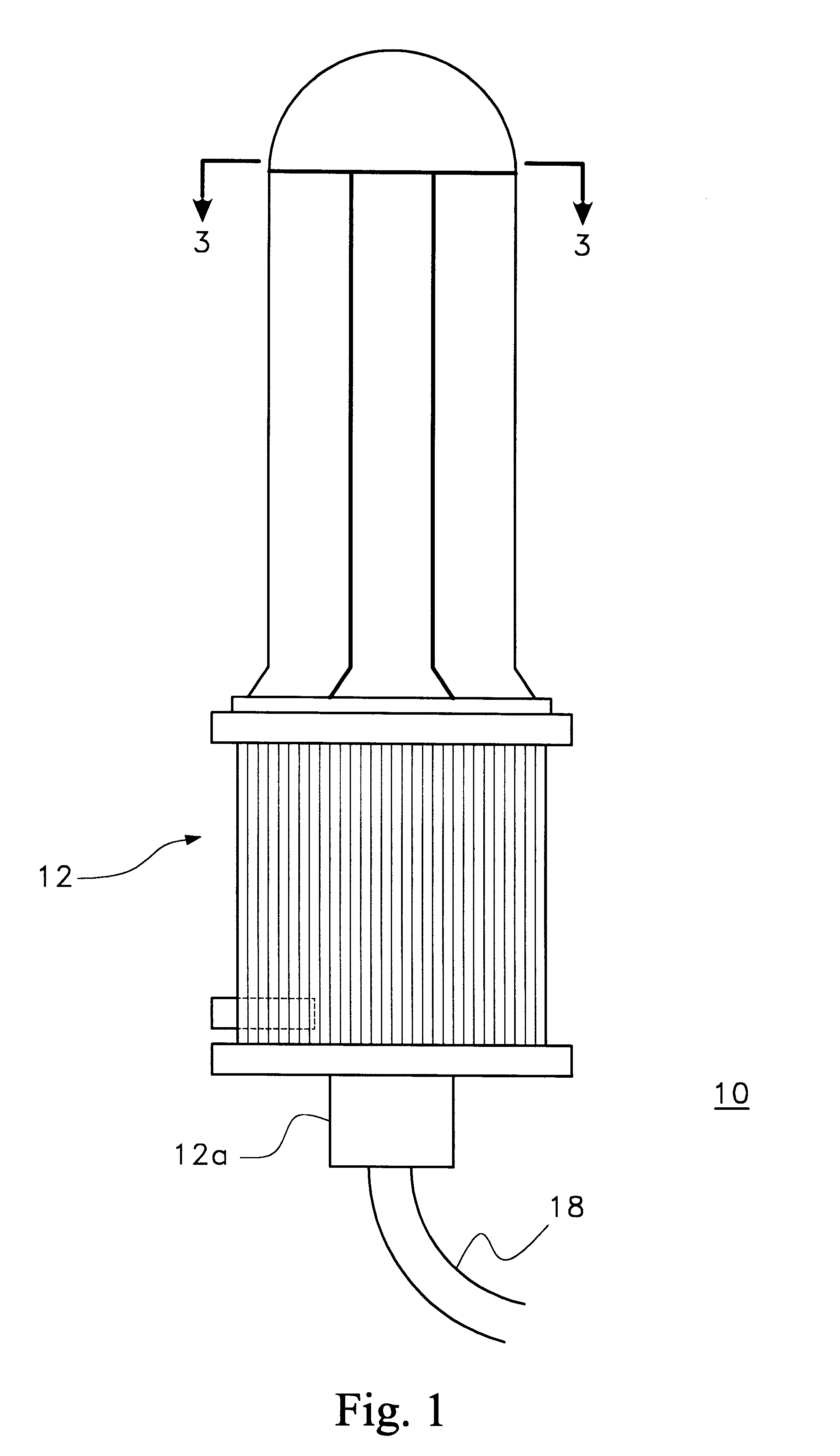
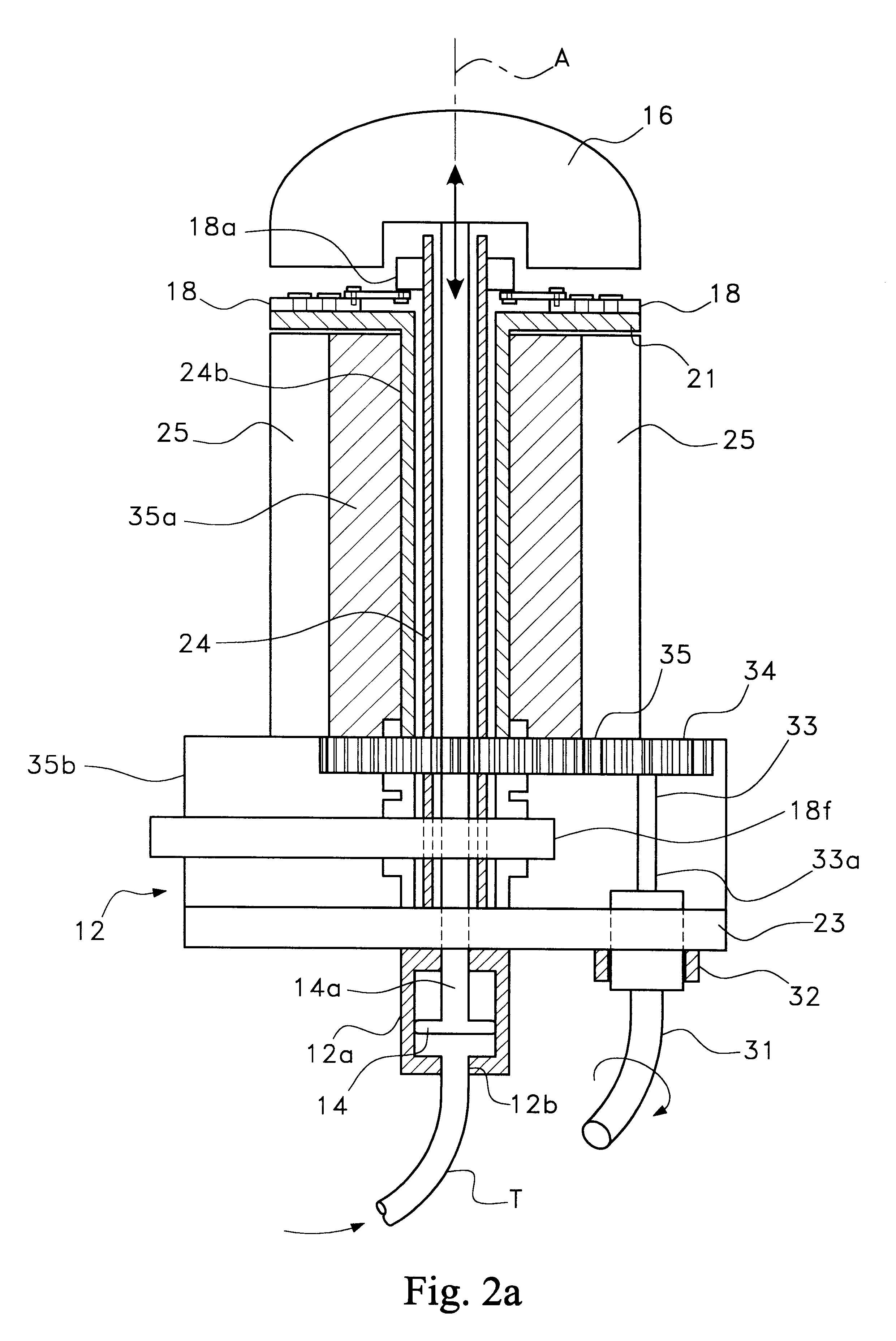
Making reference to FIGS. 1-3, there is shown therein a tool 10 designed in accordance with the principles of the present invention and comprised of a base member 12 having a centrally located, cylindrically-shaped pump chamber 12a in which a piston 14 is reciprocally mounted. A piston rod 14a is integrally joined to piston 14 and extends the length of the tool and into tip portion 16. Air under pressure is introduced from a source (not shown) through tubular member T and a bore 12b, causing piston rod 14, which extends upwardly and into the tip 16, to be lifted upon the introduction of air pressure into the lower end of chamber 12a , in the manner shown in FIG. 4d. Four (4) grip extenders 18 (see FIG. 3), provided at 90 degree intervals immediately beneath the tip 16, are extended outwardly under the control of a hollow cylinder 18a, rotatable about its longitudinal axis (see FIGS. 2a and 3). Linkage arms 18b are pivotally mounted to pivot 18e on projections 18c provided on cylinde...


PUM


Abstract

Method and apparatus for providing a socket of uniform shape within a bone preparatory to receipt of an anchoring member of an implant or augmentable bone. The tool is placed in a cavity in which a diseased bone or bone portion has been removed. A substantially cylindrical-shaped tool is inserted within the cavity. Grip extenders are selectively projected from the tool to secure the tool in place preparatory to its operation. The side walls and tip are expanded, preferably in a reciprocating fashion, compressing adjacent walls of the cavity modifying their length and width and making the sidewalls more uniform to assure precision placement of an augmented bone while providing a more uniform cavity shape and a more enriched site for a transplant, implant and / or bone augmentation. The resulting socket is scanned and a the scan is employed to prepare the augmented bone whereupon the implant may then be interfaced with the augmented bone in a highly precise manner.

Description

The present invention relates to method and apparatus for preparing a socket and more particularly to providing a method and apparatus which forms a socket of substantially uniform size and shape preparatory to receiving an implant which may be augmentable bone or a transplant.There are a number of situations requiring implantation of a prosthesis. As one particular example, when it becomes necessary to remove a diseased tooth, it is typically replaced with a prosthesis. For the last fifteen years implantologists have been resigned to adapting to an oral cavity from which the diseased tooth has been removed. The existing situation has led to a non-consistent predictability as to such implantations which result from the following five factors:1. the competency of the doctor (implantologist or prosthodontist);2. the availability of bone and the proper configuration thereof;3. the patient's immunological system and habits that may contribute to accelerated breakdown;4. the compliance o...

Claims


Application Information

Patent Timeline
IPC IPC(8): A61C8/00A61B17/88A61B17/00
CPCA61B17/8858A61C8/0089A61B2017/00544
Inventor REGNI, JR., GERALD J.
Owner REGNI JR GERALD J
Learn More