Precision taxidermy and field-use micro cutting system

Inactive Publication Date: 2001-03-20
HENDRICKSON DOYLE D
View PDF10 Cites 9 Cited by
  • Summary
  • Abstract
  • Description
  • Claims
  • Application Information

AI Technical Summary

Benefits of technology

Accordingly, the present invention provides a single hole, tailless frame member with a foldable blade body with a replacement blade to create a foldable cutting surface which is designed to self center the hide after it is separated from the upper viscera and while it is being cut in a taxidermy operation. Through appropriate design the cutting instrument achieves methods of

Problems solved by technology

Each of these actions, and indeed each animal and location on the animal, can have specific requirements and unique challenges.
This can be particularly challenging in a caping operation.
In this type of operation not only is the need for a uniform and continuous cut desired, but there is the challenge of seemingly inevitable binding and fouling of the instrument as the cut proceeds causing uneven cutting.
As mentioned, the problems which this unique field has faced range from the practical to the operational.
On the operational side, the need for accurate and clean incisions has been somewhat of a challenge because in a taxidermy operation, unlike a medical-type of operation, hair and the like is not to be removed prior to making the incision.
The degree to which the taxidermy field has viewed its own problems as unique to it is evidenced to some degree by the fact that a variety of other cutting inventions have been made in other fields and yet their various features have not,

Method used


Image

  • Precision taxidermy and field-use micro cutting system
  • Precision taxidermy and field-use micro cutting system
  • Precision taxidermy and field-use micro cutting system

Examples


Example

As can be easily understood, the basic concepts of the present invention may be embodied in a variety of ways. It involves both taxidermy techniques as well as instruments to accomplish the task. In this application, the techniques are disclosed as part of the results shown to be achieved by the various instruments described and as steps which are inherent to utilization. They are simply the natural result of utilizing the instrument as intended and described. In addition, while some device designs are disclosed, it should be understood that these not only accomplish certain methods, but also can be varied in a number of ways. Importantly, as to all of the foregoing, all of these facets should be understood to be encompassed by this disclosure.

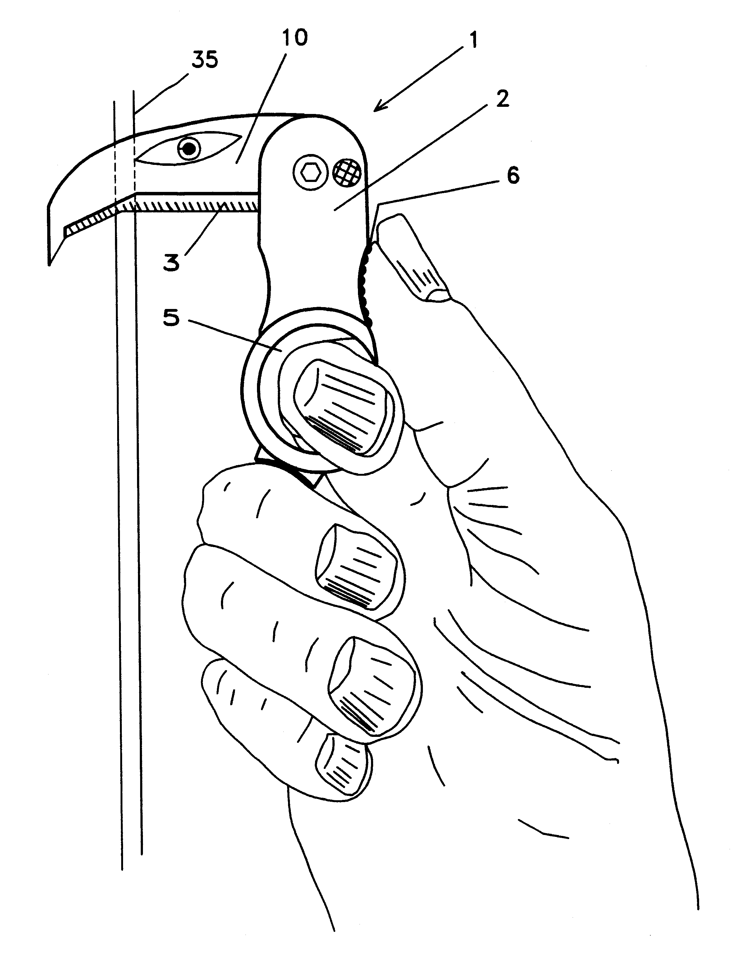
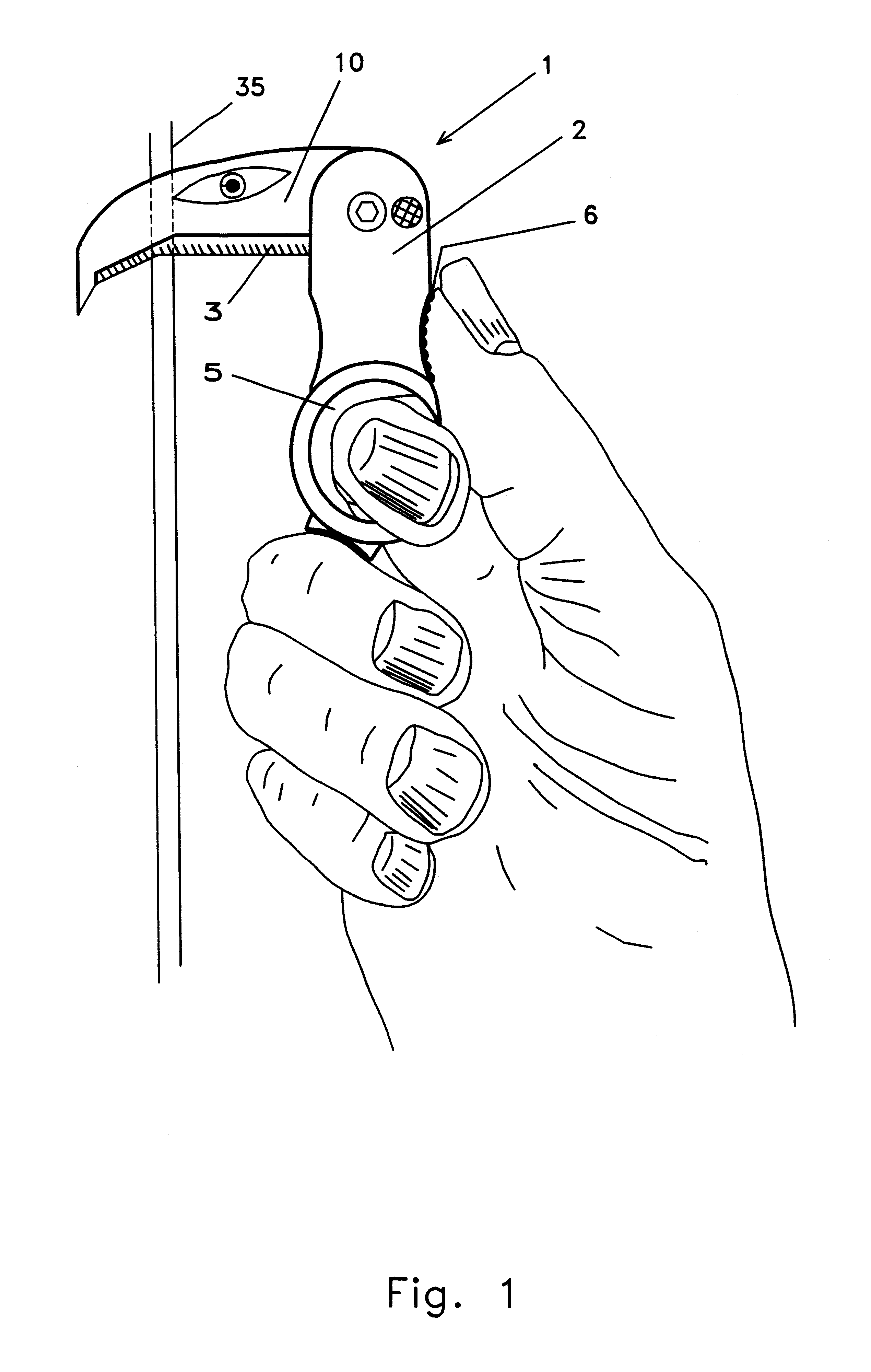
The basic concepts of the present invention may be embodied in many different ways. FIG. 1 shows a device or cutting system according to the present invention as it is designed to be used and held. This side view shows how the cutting instrume...


PUM


Abstract

A precision micro taxidermy cutting instrument is provided which includes a single hold tailless frame member to which a pivotable body member is attached. The body member can provide a blade element which is concave and through which a lifting edge which cuts and a retention edge which cuts can both combine to provide a centering feature. This centering feature can be enhanced by blade body designs which also center through the use of an offset concave element. A chisel element can separate the hide from the viscera and through the selection of appropriate angles and the like, a continuous and precise cut can be made in taxidermy operations. The frame member can include a thumb rest as well as a rotational restraining element which are diametrically opposed and which can present roughly orthogonal forces. Flared separators can be included on the blade body member to further enhance the operation of the device. The open design, trademark named the "Flying Eagle(TM)" feature is also provided through a variety of releasable locking mechanisms which permit pivoting and locking in place at various locations.

Description

I. BACKGROUND OF THE INVENTIONIn general, this invention relates to the field of taxidermy cutting instruments, namely, those instruments which are used in the cutting and mounting of animals. Specifically, it relates to such instruments as they can be used for professional taxidermy purposes as well as portable instruments such as may be appropriate for field use. It also provides novel methods through which taxidermy functions can be achieved. These functions can include field dress cutting and actions appropriate to the preparation and preservation of the results of hunting activities.Taxidermy is a field which likely has been in existence since man first learned how to hunt. Certainly its techniques and instruments have been the subject of improvement for many years. Throughout this century a number of improvements have been created which relate to the specific instruments used in taxidermy-type of applications. Over 40 years ago, M. V. Cromoga invented a skinning knife. This de...

Claims


Application Information

Patent Timeline
IPC IPC(8): A22B5/16A22B5/00B26B1/00B26B1/04
CPCA22B5/168B26B1/046
Inventor HENDRICKSON, DOYLE D.
Owner HENDRICKSON DOYLE D
Why Eureka
Try Eureka