Centrifugal gravity habitation torus constructed of salvaged orbital debris

a technology of orbital debris and centrifugal gravity, which is applied in the direction of cosmonautic vehicles, cosmonautic crew accomodations, transportation and packaging, etc., can solve the problems of eluded space launch industry passenger traffic, cost billions of dollars to construct and operate, and the cost of orbital transportation and the hardware required

Inactive Publication Date: 2001-03-27
TAYLOR THOMAS C
View PDF18 Cites 59 Cited by
  • Summary
  • Abstract
  • Description
  • Claims
  • Application Information

AI Technical Summary

Problems solved by technology

Space is an emerging economic frontier for mankind, but the cost of transportation into orbit and the hardware required for habitation once in orbit have been a barrier to commercial exploitation.
So far, however, passenger traffic has eluded the space launch industry.
The ex...

Method used


Image

  • Centrifugal gravity habitation torus constructed of salvaged orbital debris
  • Centrifugal gravity habitation torus constructed of salvaged orbital debris
  • Centrifugal gravity habitation torus constructed of salvaged orbital debris

Examples


second embodiment

FIG. 6 is an perspective view of a torus ring connected by connection modules 44 to form a 300 foot diameter torus capable of rotating 2 revolutions per minute to provide 20 to 23% of normal Earth gravity to inhabitants inside the rotating torus.

The torus is set in motion by a set of small attitude control propulsion systems spaced 180 degrees apart from each other on the torus outer surface. Some natural rotation is expected in orbit along with a gravity gradient stability with the long axis pointing toward the center of the earth. The attitude control propulsion system is also capable of correcting the slight tendency of the torus to wobble, until counter-rotating torus units are able to work together. Rotation rates from about 1 rpm to about 3 rpm are within the structural capability of the torus and the human body's ability to adapt to the environment without some discomfort. At rotation rates much above 3 rpm, people would begin to notice a Coriolis effect and experience some d...

third embodiment

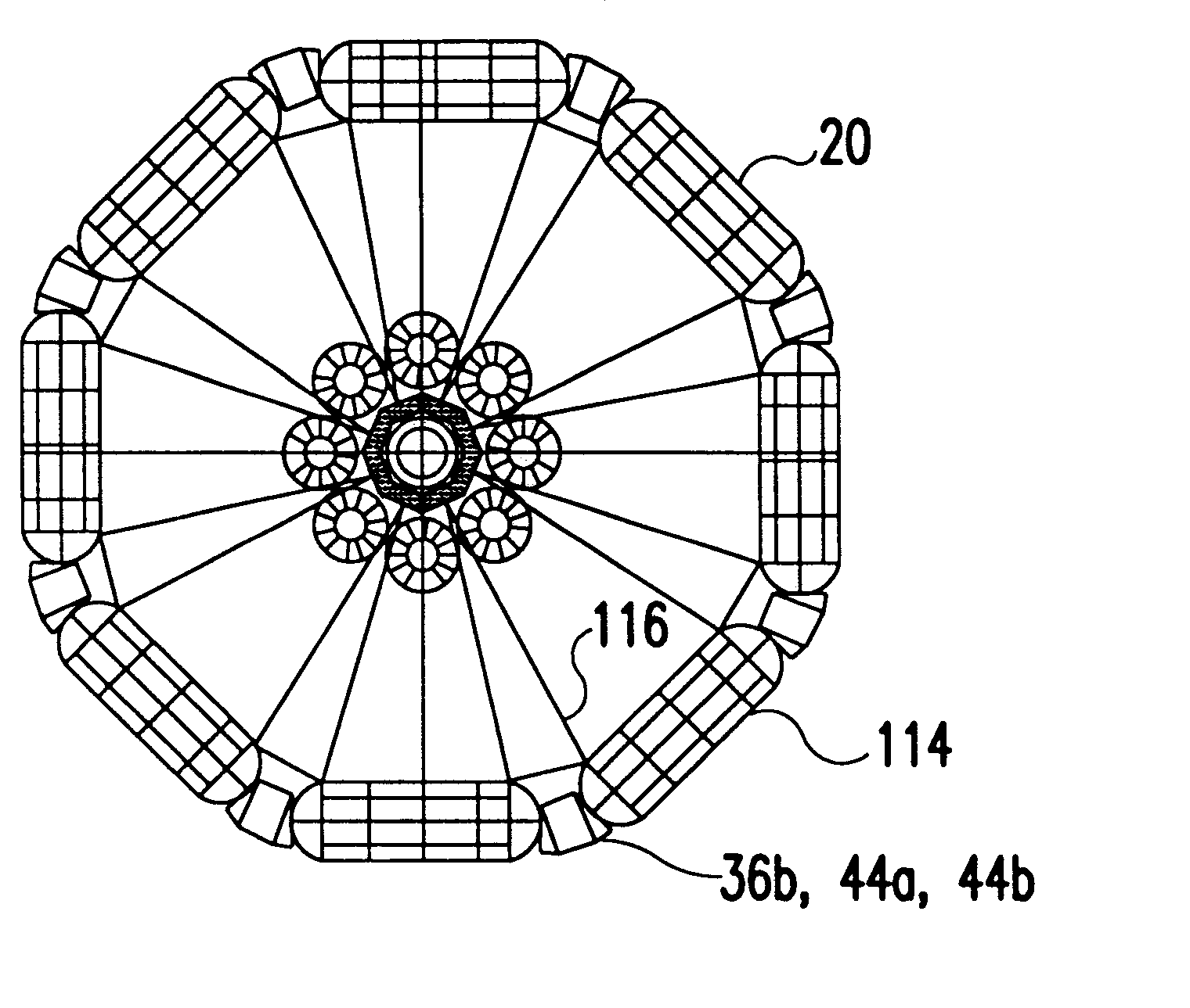
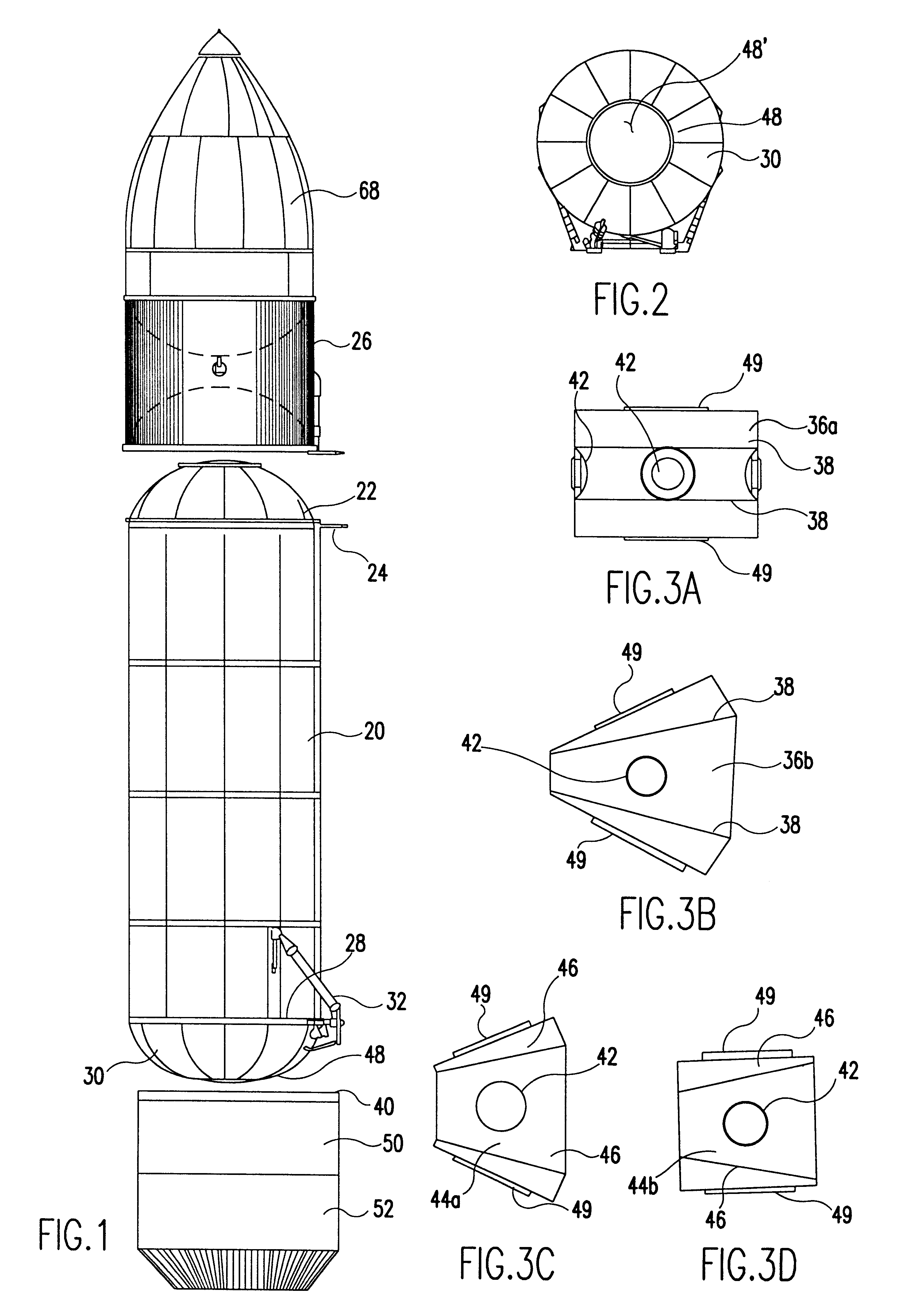
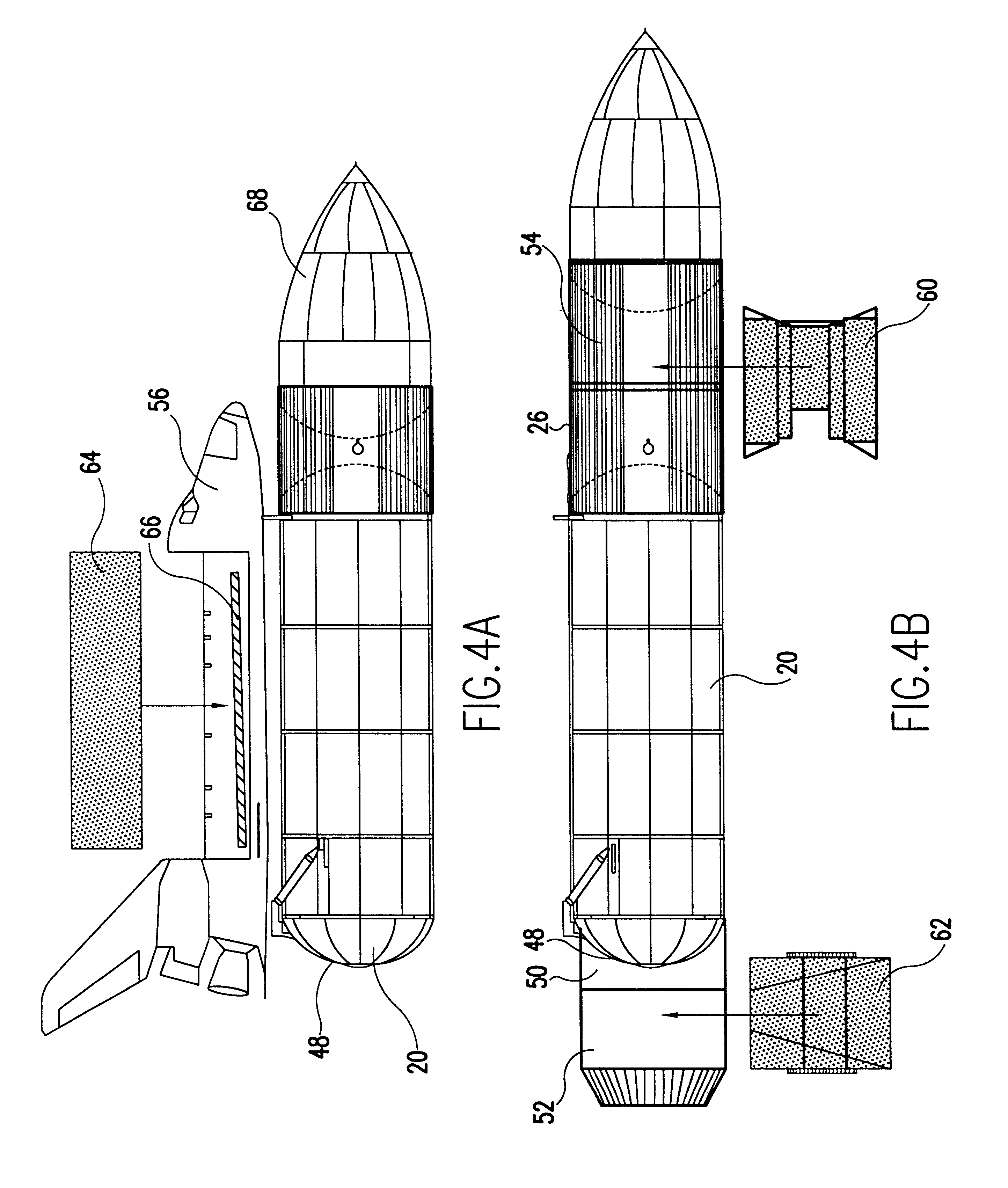
FIG. 7A shows a top view of a torus assembled from hydrogen tanks 20. A similar torus could be derived from other derelict launch debris. The hydrogen tanks 20 are converted and connected together in an eight ring torus made up from straight line segments 114 approximately 100 feet long. The straight line segments 114 are connected with connection modules 44a to form an approximately 300 foot diameter torus ring with approximately one half a million cubic feet inside, and capable of rotation at 2 rpm for a centrifugal force created artificial gravity. Critical connecting locations use large connection module 36a to perform a de-spin function to permit the transfer of passengers, a transition to the torus at the center of the torus, and other functions. Connector passengerways 100 connect the microgravity core to the simulated gravity (approximately 20% of normal Earth gravity) created in the torus as it rotates. Eight connector passengerways 100 connect the structural ring of eight ...


PUM


Abstract

An aerospace hardware derelict item is salvaged in space, modified, and reused to provide manned facilities in orbit. The hardware packages added onto the salvaged discarded item enhances its value, and incorporates at least the subsystems required to effectively reuse portions of previously discarded launch vehicle components, and other derelict objects in space. The hardware, and technique used reduces the cost of launching comparable hardware to orbit, because of the reuse, and provides a human habitation in orbit. The salvaged items include the external tank of the space shuttle, other derelict orbital hardware, the add-on cargo pod in two forms, and the ability to convert the derelict into a cost effective reusable item. The salvaged hardware is initially capable of contributing mass, length, interior volume, strongback, rotational stability mass, interior pressurized volumes, artificial gravity, and stability with the addition of simple subsystems for salvage, and interior development packages.

Description

1. Field of the InventionThe present invention relates to a centrifugal gravity habitation torus constructed of salvaged orbital debris, which is a reusable aerospace structure adapted to be placed in an orbit, and is an improvement in aeronautical hardware.2. Background of the Related ArtSpace is an emerging economic frontier for mankind, but the cost of transportation into orbit and the hardware required for habitation once in orbit have been a barrier to commercial exploitation. The present cost of cargo transportation into orbit is in the range of $16,000 per pound using fully expendable and partly reusable space launch vehicles such as the space shuttle. A reduction in the cost of space transportation into orbit using fully reusable vehicles is on the threshold of development, and could shortly reduce the transportation costs to one-tenth their present levels.The result of this type of cost reduction will be similar to the effect a similar cost reduction had on the aircraft ind...

Claims


Application Information

Patent Timeline
IPC IPC(8): B64G1/12B64G1/22B64G1/00B64G1/60B64G1/64B64G1/56
CPCB64G1/12B64G1/60B64G1/56B64G1/64
Inventor TAYLOR, THOMAS C.
Owner TAYLOR THOMAS C
Why Eureka
Try Eureka