Trailer control valve for a compressed air brake system for motor vehicles

a technology of brake system and control valve, which is applied in the direction of brake system, vehicle components, brake components, etc., can solve the problems of relatively expensive construction measures

Inactive Publication Date: 2001-03-27
KNORR-BREMSE SYST FUER NUTZFAHRZEUGE GMBH
View PDF9 Cites 54 Cited by
  • Summary
  • Abstract
  • Description
  • Claims
  • Application Information

AI Technical Summary

Benefits of technology

The trailer control module according to the invention has an advantage over the prior art that the structural costs are reduced considerably by means of eliminating the second control chamber with its control piston. Nevertheless, it is assured, however, that in any case, a control piston is available, independent of which control circuit a control pressure is used from. In addition, the directional control valves of an extremely simple design that are inserted into a corresponding circuit arrangement are sufficient in order to generate a control pressure in the electrical control circuit using the compressed air reservoir associated with the auxiliary brake system and to modulate this control pressure, for example as a function of load or brake slip.Advantageous improvements and updates of the trailer control module are possible by means of the measures taken hereinafter.In the improvement of the invention disclosed herein, simple means are used to achieve the fact that in the event of a failure of the electrical control circuit, the control pressure of the pneumatic control circuit can come into play on the one control piston.Finally, the measure disclosed herein produces a component in which the electrical and mechanical means are united that are required for directly controlling the one control piston.

Problems solved by technology

However, if the control pressure generated in the electrical part of the braking power transmitter fails, then the other control pressure comes into play in the control chamber of the relay valve by means of reversing the valve.
Viewed on the whole, measures that are relatively costly in terms of construction are taken in order to maintain the function of the trailer control valve, for an unlikely defect of the electrical control circuit.

Method used


Image

  • Trailer control valve for a compressed air brake system for motor vehicles
  • Trailer control valve for a compressed air brake system for motor vehicles
  • Trailer control valve for a compressed air brake system for motor vehicles

Examples


Embodiment Construction

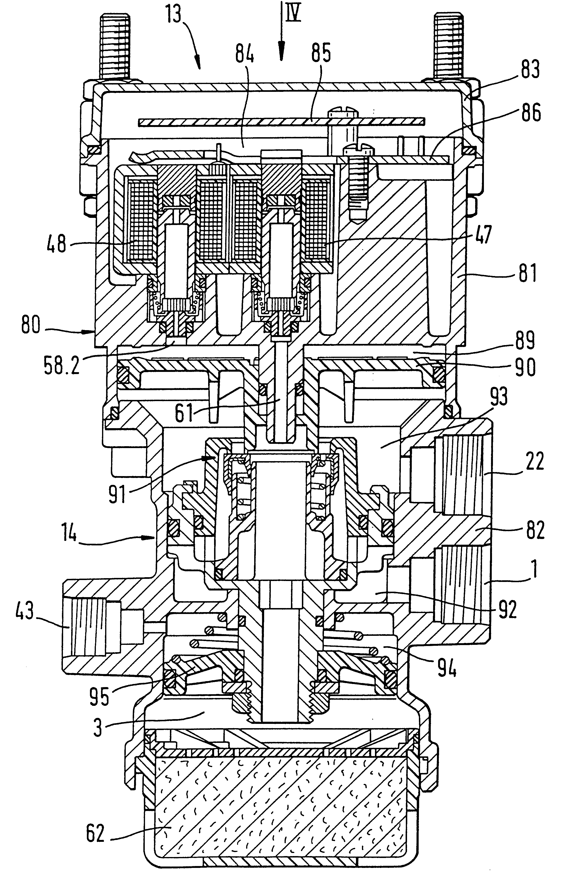
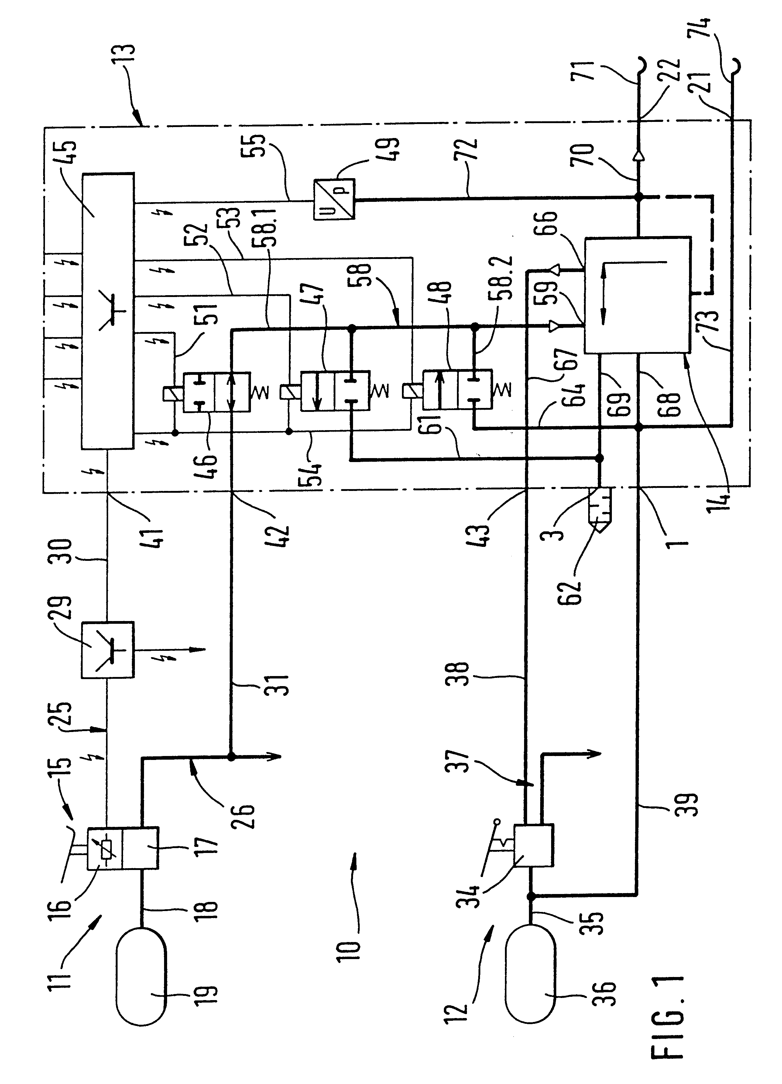
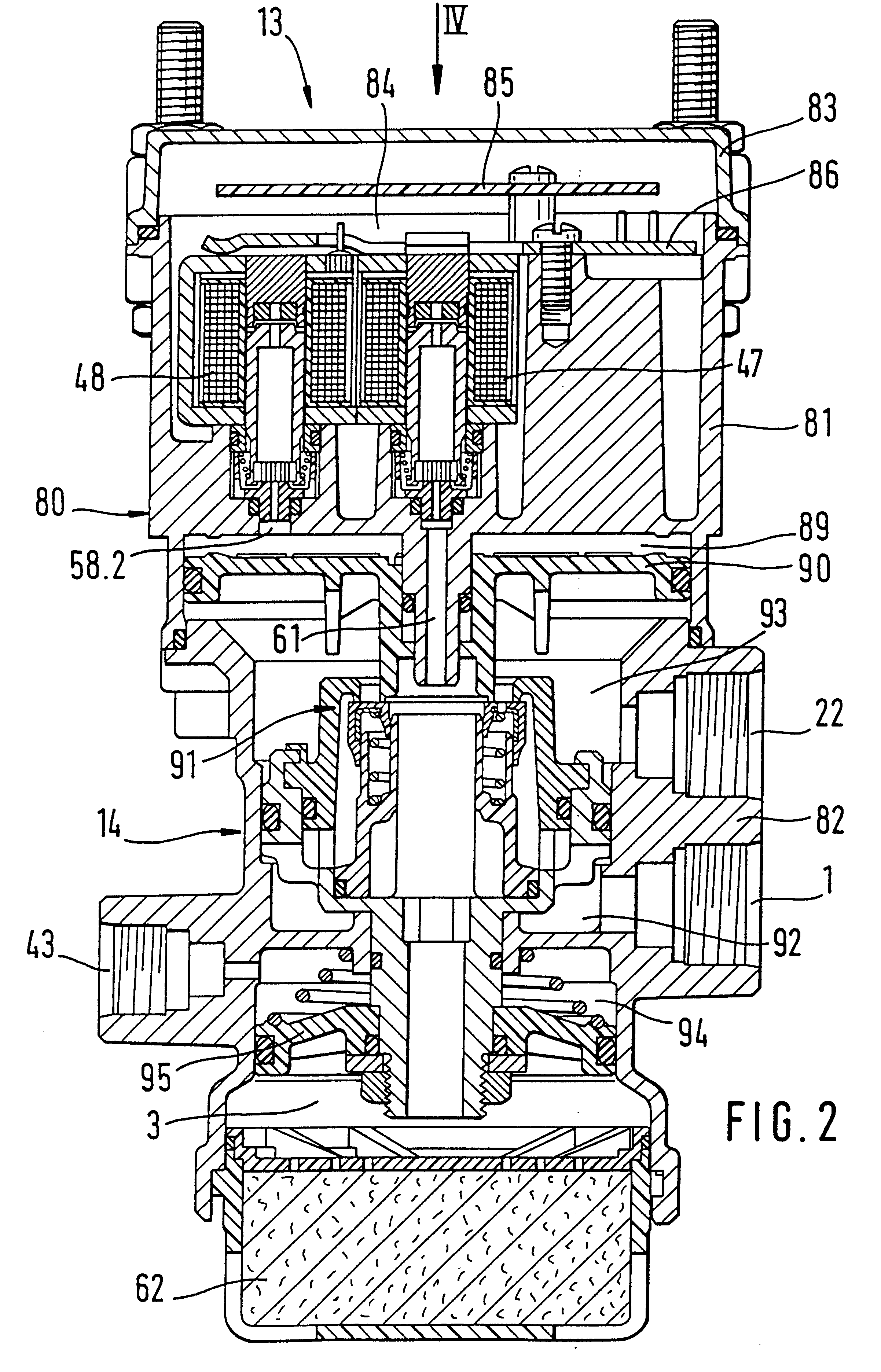
A dual-circuit, dual-line, externally powered compressed air brake system 10, which is only partially schematically depicted in FIG. 1, has a service brake system 11, an auxiliary brake system 12, and a trailer control module 13 (called module below) with a trailer control valve 14. The compressed air brake system 10 is disposed on a pulling vehicle; it is provided for trailer operation.

The service brake system 11 has a foot-actuated braking power transmitter 15 with an electrical part 16 and a pneumatic part 17. The part 17 of the braking power transmitter 15 communicates with a compressed air reservoir 19 by way of a reservoir line 18.

The braking power transmitter 15 is connected with its electrical part 16 to an electrical control circuit 25 and is connected with its pneumatic part 17 to a pneumatic control circuit 26 of the service brake system 11. The electrical control circuit 25 can be used for the control of a brake circuit, not shown, which is associated with the rear axle ...


PUM


Abstract

A trailer control valve having control pistons for actuating a double seat valve, which can control the communication between a compressed air reservoir, a compressed air consumer, and a pressure relief location. In order to structurally simplify the trailer control valve, a control piston is provided that is jointly associated with an electrical control circuit and a pneumatic control circuit of a service brake system. Furthermore, a valve is provided that is connected to the pneumatic control circuit of the service brake system, which closes the pneumatic control circuit of the service brake off from to the trailer control valve when the electrical control circuit is functional, and in the event of a failure of the electrical control circuit, unblocks the pneumatic control circuit of the service brake system.

Description

PRIOR ARTEP 0 110 119 A1, FIG. 4 and EP 0 547 407 A1 have disclosed a relay valve whose control chamber can be controlled with control pressures conveyed from two control circuits of an electronically controlled compressed air brake system for motor vehicles. The relay valve is connected to at least one brake cylinder of the vehicle. The two control pressures can be generated with an actuation of the braking power transmitter, a control pressure in an electrical part of the braking power transmitter and a control pressure in a pneumatic part. Each control pressure can take the place of the other. However, since the control pressure generated in the electrical part of the braking power transmitter should be the leading one, in the presence of this control pressure, the other control pressure generated in the pneumatic part of the braking power transmitter is held back by means of a reversing valve disposed upstream of the control chamber of the relay valve. However, if the control pr...

Claims


Application Information

Patent Timeline
Patent Type & Authority Patents(United States)
IPC IPC(8): B60T13/58B60T13/24B60T8/32B60T13/10B60T15/00B60T15/02B60T8/36B60T13/68
CPCB60T8/327B60T8/361B60T13/24B60T13/58B60T15/027
Inventor KAISERS, OLAFSCHAFFERT, EBERHARD
Owner KNORR-BREMSE SYST FUER NUTZFAHRZEUGE GMBH
Why Eureka
Try Eureka