Ostomy appliance with inverted triangular faceplate and non-protruding pull tabs

Inactive Publication Date: 2001-03-27
HOLLISTER INCORPORAED
View PDF12 Cites 42 Cited by
  • Summary
  • Abstract
  • Description
  • Claims
  • Application Information

AI Technical Summary

Benefits of technology

Where provided, such pull tabs almost always project upwardly, that is, towards the upper ends of the pouches, to render them more readily accessible in use, but such a location has offsetting disadvantages. Because of manufacturing requirements, the perimeter of a faceplate (including its tab portion) must necessarily be spaced inwardly from the periphery of the pouch on which the faceplate is mounted, with the result that a faceplate having upwardly protruding tabs must be located lower along the pouch wall than if such tabs were omitted. For any given size of pouch, that means that the provision of upwardly-projecting tabs reduces the effective volumetric capacity of the pouch. Also, the tab for a backing layer that extends upwardly away from the remainder of the faceplate may be exposed for possible contact with clothing and present the risk that such contact might initiate unintentional detachment of the faceplate from the skin.
It is therefore a main aspect of this invention to provide an ostomy appliance having an adhesive faceplate shaped and oriented to provide more effective adhesive attachment where it is needed most in resisting pulling forces in use, while reducing the area of adhesive attachment in the lower region of a faceplate where excessive contact might cause pinching and other patient discomforts. More specifically, the faceplate of the appliance is of inverted triangular shape having rounded corners, with one of the corners facing downwardly towards the lower end of the pouch and one of its side edges facing upwardly along the upper end of the pouch. The result is an appliance having a faceplate of greater width in its upper region (i.e., above the midpoint of its stoma-receiving opening) than in its lower region, thereby providing greater adhesion where it is needed most, reducing the size of the faceplate in its lower region to promote greater patient comfort, and also limiting material volume and expense (recognizing that hydrocolloid-containing adhesive compositions

Problems solved by technology

For any given size of pouch, that means that the provision of upwardly-projecting tabs reduces the effective volumetric capacity of the pouch.
Also, the tab for a backing layer that extends upwardly a

Method used


Image

  • Ostomy appliance with inverted triangular faceplate and non-protruding pull tabs
  • Ostomy appliance with inverted triangular faceplate and non-protruding pull tabs

Examples


Embodiment Construction

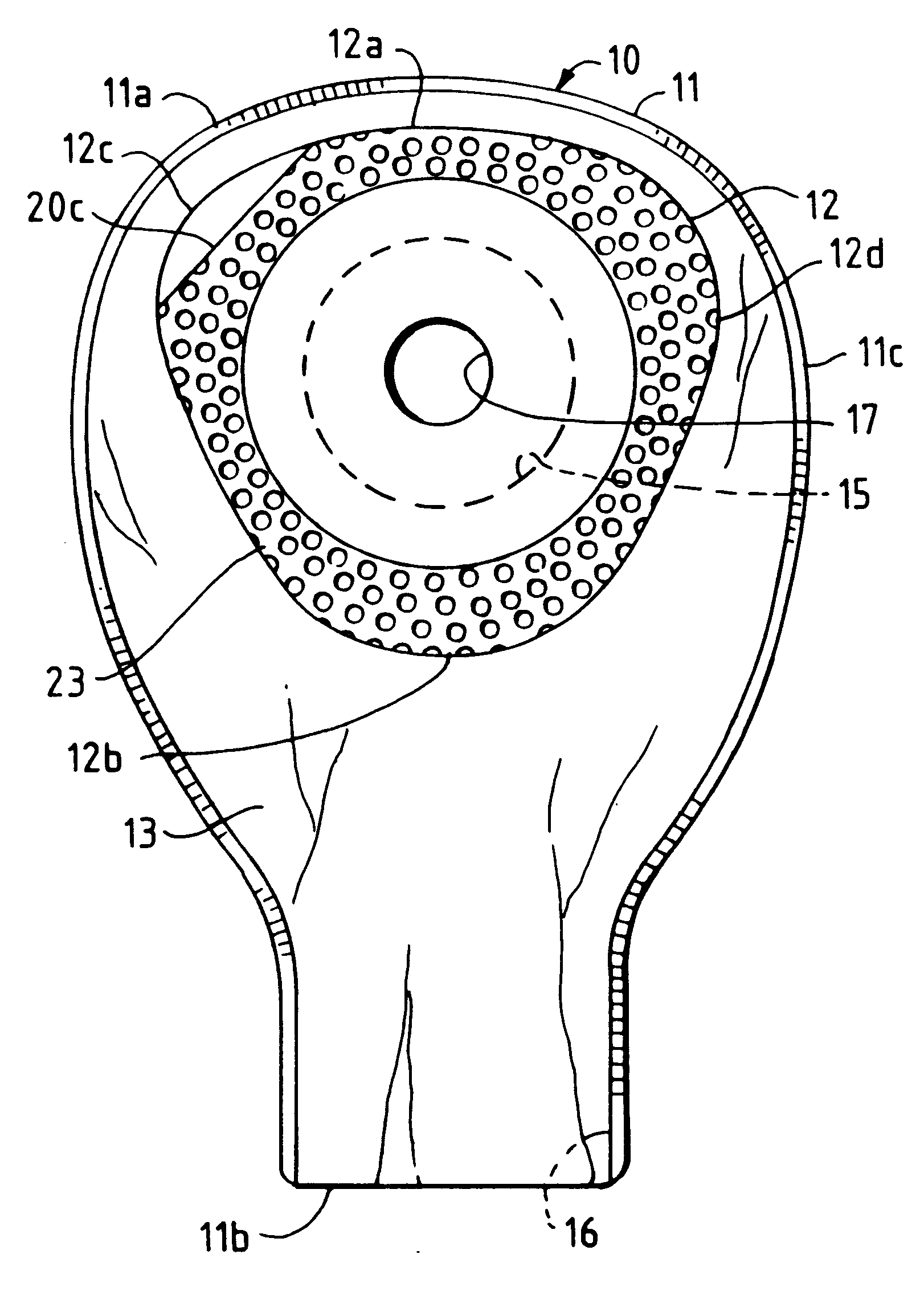
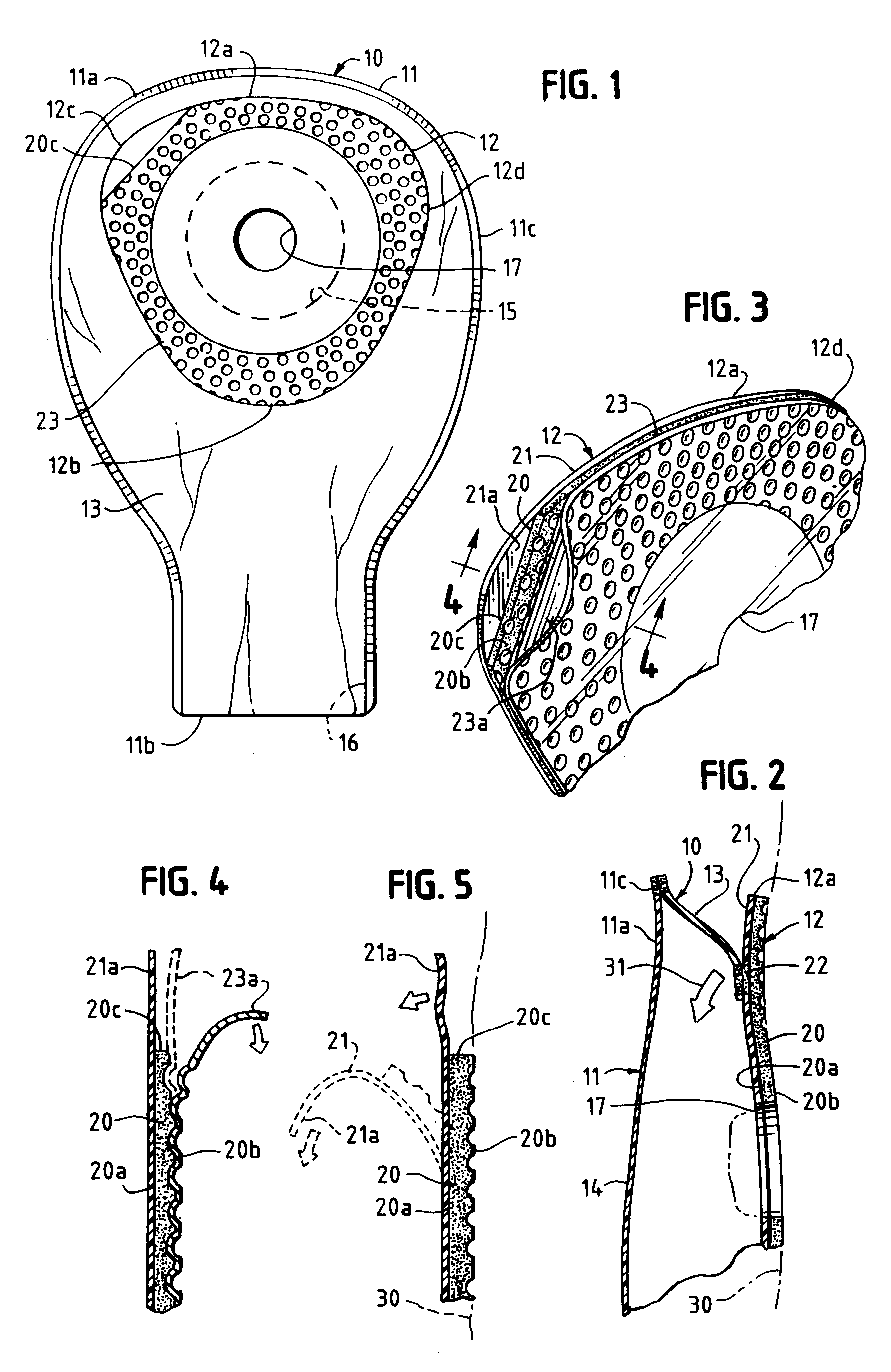
Referring to the drawings, the numeral 10 designates an ostomy appliance consisting essentially of a pouch 11 and a faceplate 12. The drawings depict what may be referred to as a one-piece appliance, such term being commonly used to mean a unitary appliance having a faceplate intended to be adhesively secured directly to the peristomal skin surfaces of a wearer. It is to be noted, however, that at least some of the advantages of this invention might be obtained if used in a two-piece appliance in which the pouch and its adhesive faceplate are intended to be adhesively attached to (and detached from) the surface of a mounting ring which in turn is adhesively attached to such peristomal skin surfaces. Therefore, the term "appliance," as here used is meant to include not only a one-piece ostomy appliance but also the pouch / faceplate component of a two-piece adhesively-coupled appliance.

Pouch 11 has upper and lower ends 11a and 11b, respectively and is typically composed of two panels o...


PUM


Abstract

An ostomy appliance is disclosed in which the adhesive faceplate for holding the appliance in place is of inverted triangular shape with rounded corners. The faceplate includes an adhesive layer composed of a hydrocolloid-containing pressure-sensitive adhesive, a protective release sheet removably covering the bodyside surface of the adhesive layer, and a flexible backing layer covering the opposite (pouchside) surface of the adhesive layer and permanently securing the faceplate to an ostomy pouch about the perimeter of a stoma-receiving opening. Because of its orientation, the triangular faceplate has one of its side edges extending across the upper end of the pouch (i.e., facing upwardly when the pouch is worn), resulting in a construction in which the area of the faceplate's adhesive layer is wider above the faceplate's opening than below it. In a preferred embodiment, the adhesive layer is recessed or set back at one of the faceplate's upper corners to provide both the release sheet and backing layer with non-protruding tab portions that facilitate both application and removal of the appliance.

Description

BACKGROUND AND SUMMARYConventional one-piece ostomy appliances, and the pouch components of two-piece adhesively-coupled appliances, generally consist of collection pouches equipped with adhesive faceplates of various shapes for adhering the appliances to the peristomal skin surfaces of patients or to the attachment surfaces of mounting rings adhesively secured to such peristomal surfaces. Most commonly, the faceplates have outer margins that are either generally round or square (with rounded corners) as shown, for example, in U.S. Pat. Nos. 5,403,299 and 4,213,458, although faceplates having other outlines are also known (see, for example, U.S. Pat. No. 5,811,116). Regardless of its shape, such a faceplate essentially consists of an adhesive layer, preferably of a hydrocolloid-containing adhesive capable of absorbing moisture and having both wet and dry tack, and a backing layer of polymeric film or fabric covering the backside (pouchside) surface of the adhesive layer and securing...

Claims


Application Information

Patent Timeline
IPC IPC(8): A61F5/445A61F5/448
CPCA61F5/448
Inventor KAVANAGH, SEAMUS T.DIXON, ROBERT T.MCGUINNESS, GARRETT B.
Owner HOLLISTER INCORPORAED
Why Eureka
Try Eureka