Intake duct

a technology of intake duct and intake air, which is applied in the direction of combustion engine, combustion air/fuel air treatment, charge feed system, etc., can solve the problems of increased space needed, offensive to motor vehicle passengers, and inconvenient operation of the intake system

Inactive Publication Date: 2001-04-03
TOYODA GOSEI CO LTD
View PDF5 Cites 29 Cited by
  • Summary
  • Abstract
  • Description
  • Claims
  • Application Information

AI Technical Summary

Problems solved by technology

Intake systems used with motor vehicle engines generate noise in conjunction with the intake of air.
This intake noise is offensive to persons in the motor vehicle, particularly when the engine is running at low speeds.
To install these devices in the engine compartment, increased space is needed which necessarily decreases the amount of room available for installing other parts.
The above-described method of throttling the intake passage, however, produces a problem when the engine runs at a high--speed since the amount of intake air is insufficient and lowers the engine output.
In this case, the problem is that since the acoustic mass is small, the intake noise is large even though the engine is running at a low speed, resulting in booming noise of low frequencies entering the passenger compartment of the motor vehicle.
The use of these parts increases in the total number of parts used, and also increases the complexity of the device, both of which are less favorable in terms of production costs.
When the difference between F.sub.1 and F.sub.2 is too small, the valve member flutters at the time the valve member opens the second intake passage, thus frequently causing noise.
When the difference between F.sub.1 and F.sub.2 is too large, the amount of intake air is frequently short.
This causes the problem that intake noise leaks through the gap between the valve member and second intake passage.
The above-described intake duct has the further problem that, at the time the valve member slightly opens the second intake passage, vibrations are generated in the valve member, causing the gerieration of noise.

Method used


Image

  • Intake duct
  • Intake duct
  • Intake duct

Examples


embodiment 1

(Embodiment 1)

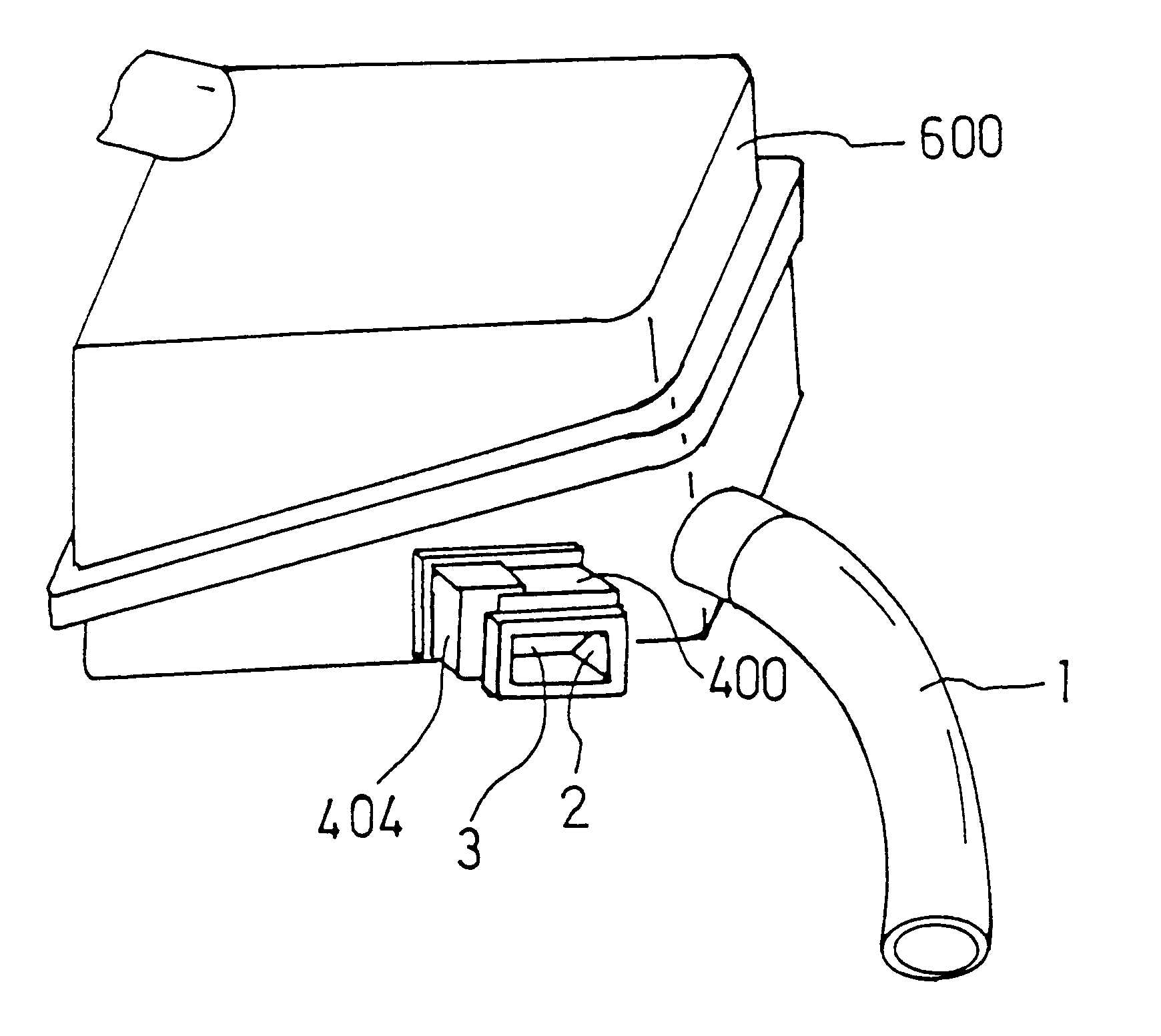
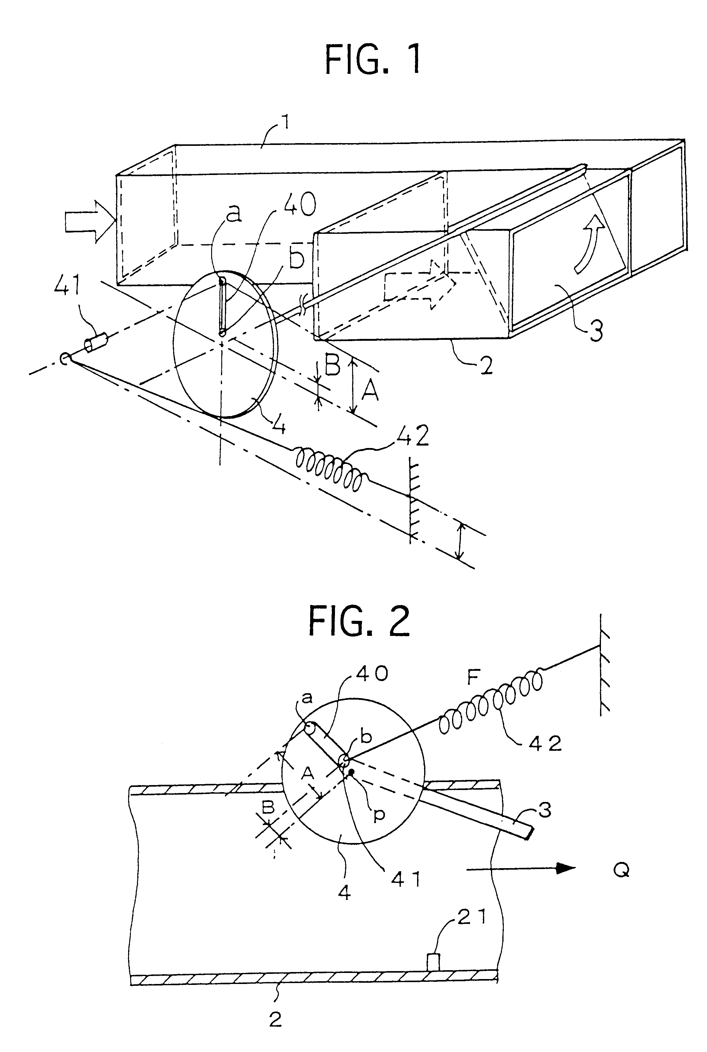
FIG. 1 is a diagram explaining an intake duct of one exemplary embodiment. As shown, a first intake passage 1, with a small diameter, and a second intake passage 2 with a diameter greater than that of the first intake passage 1 are joined to define the collective intake duct. In FIG. 1, the junction of the first intake passage 1 and second intake passage 2 is not illustrated.

The cross-sectional area of the first intake passage 1 is equal to that of a pipe of .O slashed.40, and the cross-sectional area of the second intake passage 2 is equal to that of a pipe of .O slashed.70. The distance between an open end of the first intake passage 1 and the junction between the two intake passages is made longer than that between an open end of the second intake passage 2 and the same junction. A valve member 3 is pivotably mounted on a wall defining part of the second intake passage 2.

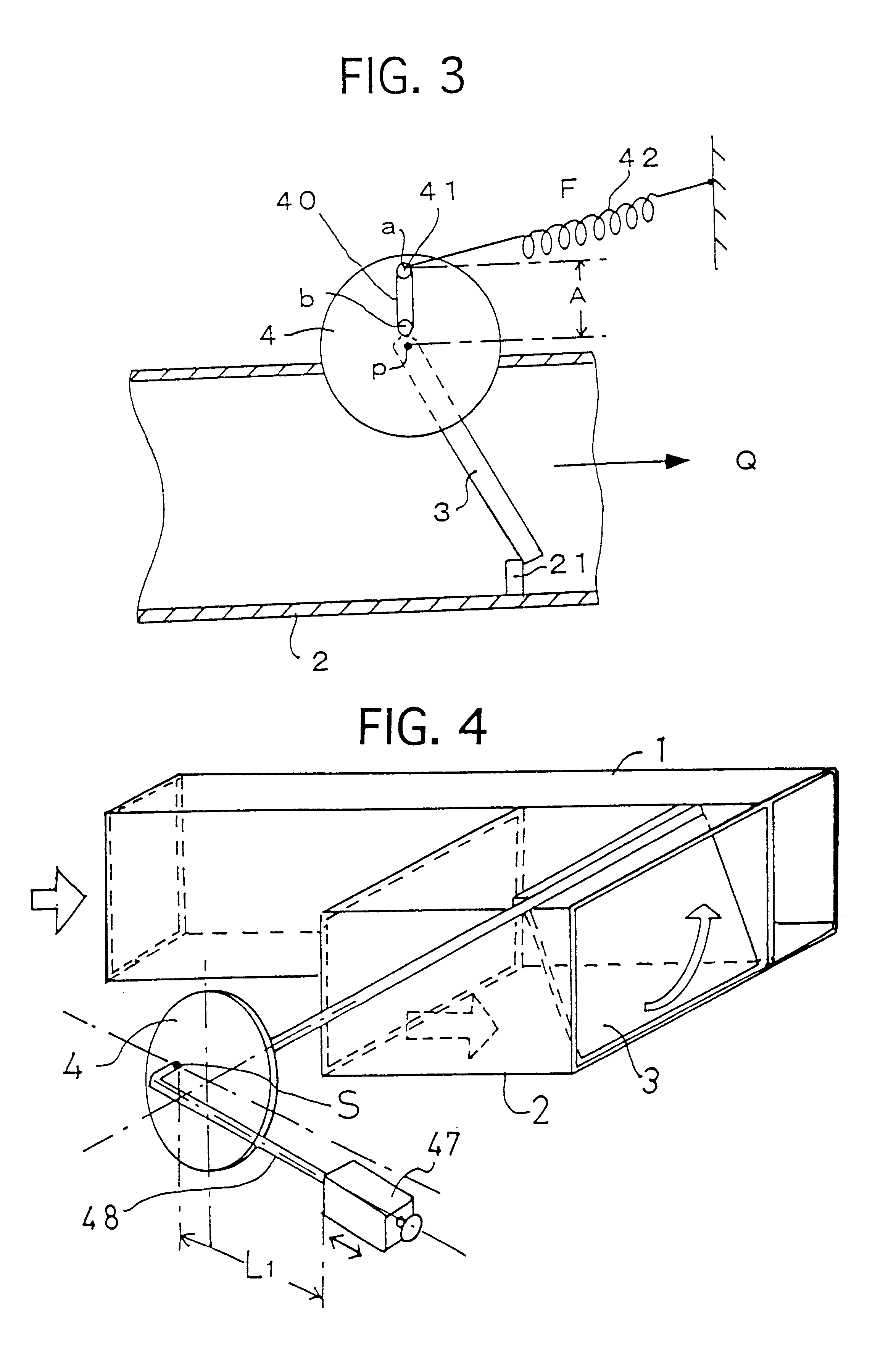
A cam 4, having a disk-like configuration, is connected at its center to a pivot shaft of the va...

embodiment 2

(Embodiment 2)

FIG. 4 illustrates a second embodiment of an intake duct in accordance with the present invention. The intake duct of the present embodiment differs from that of Embodiment 1 in that spring 42 used in Embodiment 1 is replaced with a weight 47 having a weight equal to W.

More specifically, the pivot shaft of valve 3 is still connected to the center of a cam 4 as in, Embodiment 1. One end of a rod 48 is secured to cam 4 at a fixed point (S) offset from the center (P) thereof, and weight 47 is attached to rod 48 so as to be movable thereon. In the present embodiment, the fixed offset point (S) defines a point of action.

The intake duct of the present embodiment has the arrangement that, when valve 3 fully closes the second intake passage 2, the end of rod 48 is located slightly downwardly from its horizontal position, as illustrated in FIG. 4, and the weight 47 is retained of the end of rod 48 such so that the distance "L" between weight 47 and fixed point (S) becomes the m...

embodiment 3

(Embodiment 3)

In the preceding embodiments, cam 4 used has a disk-like configuration and is secured to the pivot shaft of the valve 3, which is a conceptual arrangement. Practically, as shown in FIG. 5, a sector-shaped cam 4 is provided on one of the side walls defining the second intake passage 2 integrally with a valve 3, and one end of a spring 42 is secured to a wall partly defining the second intake passage 2. In this present embodiment, since cam 4 pivots with valve 3, torque is directly transmitted to cam 4 from valve 3. This arrangement eliminates looseness between the parts, and consequently, disadvantages such as operation lag are prevented. Furthermore, the number of parts is decreased so that production costs are reduced.

With the arrangement illustrated in FIG. 6, wherein a sector-shaped cam 4 is provided on each of side walls defining the second intake passage 2, and a spring 42 is provided in each cam 4, the pivotal movement of a valves can be more accurately controlle...


PUM


Abstract

An intake duct capable of reducing intake noise when an engine runs at a low speed and supplying a sufficiently large amount of air when the engine runs at a high speed without using any electron control circuit or electromagnetic valve, which is produced at low costs. The intake duct includes valve adjusting means which restrains the movement of the valve member when the valve member brings a second intake passage from the closed state to the open state, and facilitates the movement of the valve member when the valve member brings the second intake passage from the open state to the closed state. When the second intake passage is brought to the open state from the closed state, the restraining force of the valve adjusting means is great to restrain the movement of the valve member, and when the second intake passage is brought to the closed state from the open state, the valve member readily pivots to open the second intake passage. Thus, the valve member is free from the half-closed state, and consequently, the generation of low-frequency booming noise can be prevented.

Description

1. Field of the InventionThe present invention relates to an intake duct as a passageway adapted to supply air to an engine, and more particularly to an intake duct capable of reducing noise during use.2. Description of the Related ArtIntake systems used with motor vehicle engines generate noise in conjunction with the intake of air. This intake noise is offensive to persons in the motor vehicle, particularly when the engine is running at low speeds. Conventionally, side branches and / or resonators have been provided in such intake ducts to reduce the noise at a specific frequency, calculated, for instance, in accordance with the Helmholtz's resonance theory.However, the side branches may be as long as about 30 cm, and the resonators may have a volume as great as 14 litters. To install these devices in the engine compartment, increased space is needed which necessarily decreases the amount of room available for installing other parts.Japanese Utility Model application laid-open No. S...

Claims


Application Information

Patent Timeline
Patent Type & Authority Patents(United States)
IPC IPC(8): F02B27/02F02M35/10F02M35/12
CPCF02M35/10013F02M35/10301F02M35/1222
Inventor KOMADA, MINORUFUJIHARA, KAZUOHIROSE, YOSHIKAZUKOMORI, TAKAHIROKINO, HITOSHIISHIHARA, HIDETOSHI
Owner TOYODA GOSEI CO LTD
Why Eureka
Try Eureka