Variable delivery fuel supply device

a fuel supply device and variable technology, applied in the direction of positive displacement liquid engines, electric control, machines/engines, etc., can solve the problems of abnormal increase of fuel pressure, and breakdown of structural elements forming the high-pressure fuel passag

Inactive Publication Date: 2001-04-03
MITSUBISHI ELECTRIC CORP
View PDF7 Cites 18 Cited by
  • Summary
  • Abstract
  • Description
  • Claims
  • Application Information

AI Technical Summary

Problems solved by technology

However, since there is a limit in the response characteristics of the electromagnetic valve, a fuel pressure in the delivery pipe 2 may increase abnormally depending on operational conditions of the internal combustion engine.
This caused an abnormal increase of fuel pressure in the high-pressure fuel passage such as the delivery pipe 2, whereby structural elements constituting the high-pressure fuel passage might be broken.
Further, even when the electromagnetic valve correctly operated, there was difficulty in estimating practically a fuel pressure in the delivery pipe 2 or the fuel pump in a course of raising a fuel pressure in the delivery pipe 2 to a pred

Method used


Image

  • Variable delivery fuel supply device
  • Variable delivery fuel supply device
  • Variable delivery fuel supply device

Examples


first embodiment

The variable delivery fuel supply device according to the present invention will be described with reference to FIGS. 1 to 3 wherein the same reference numerals designate the same or corresponding parts.

embodiment 1

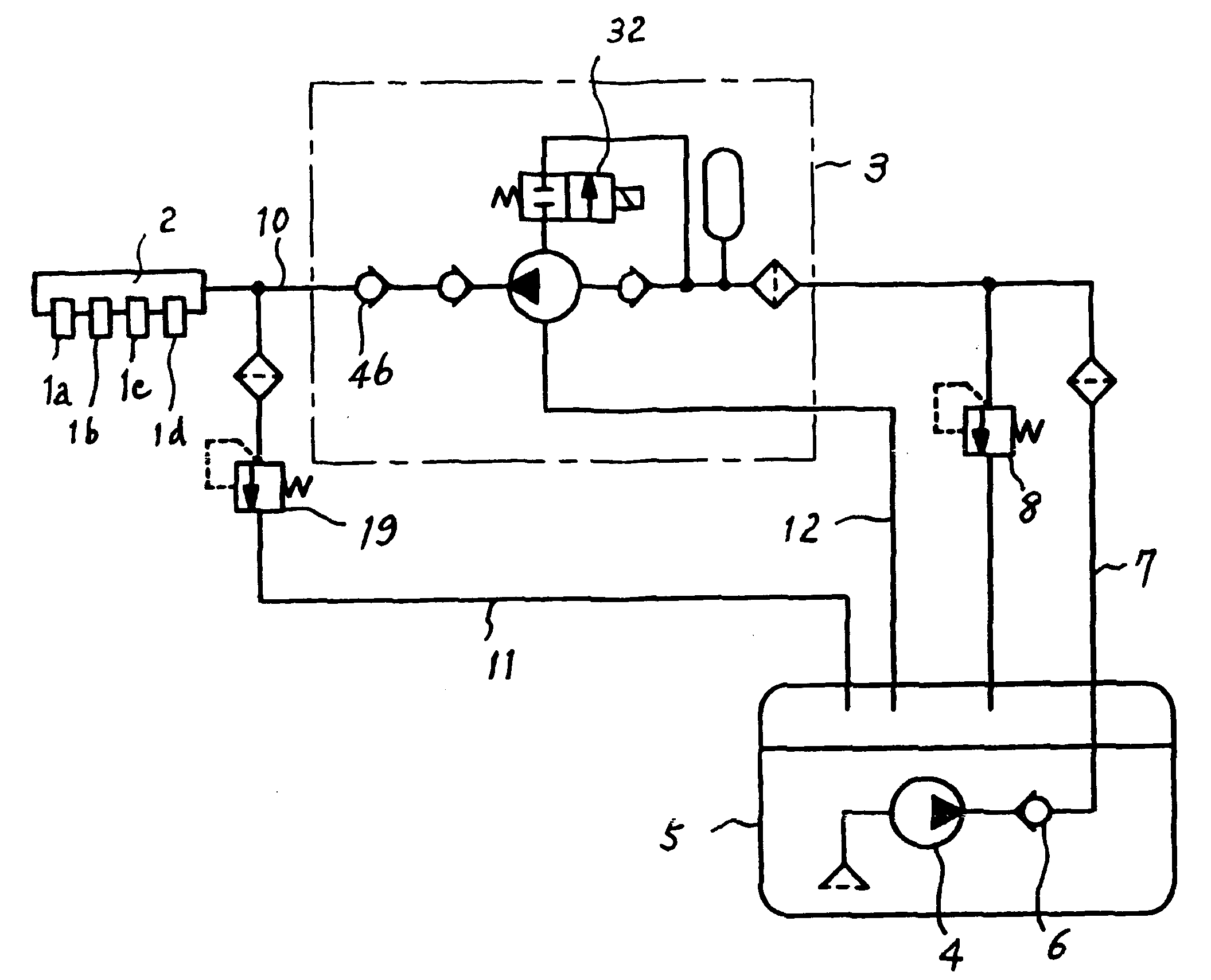
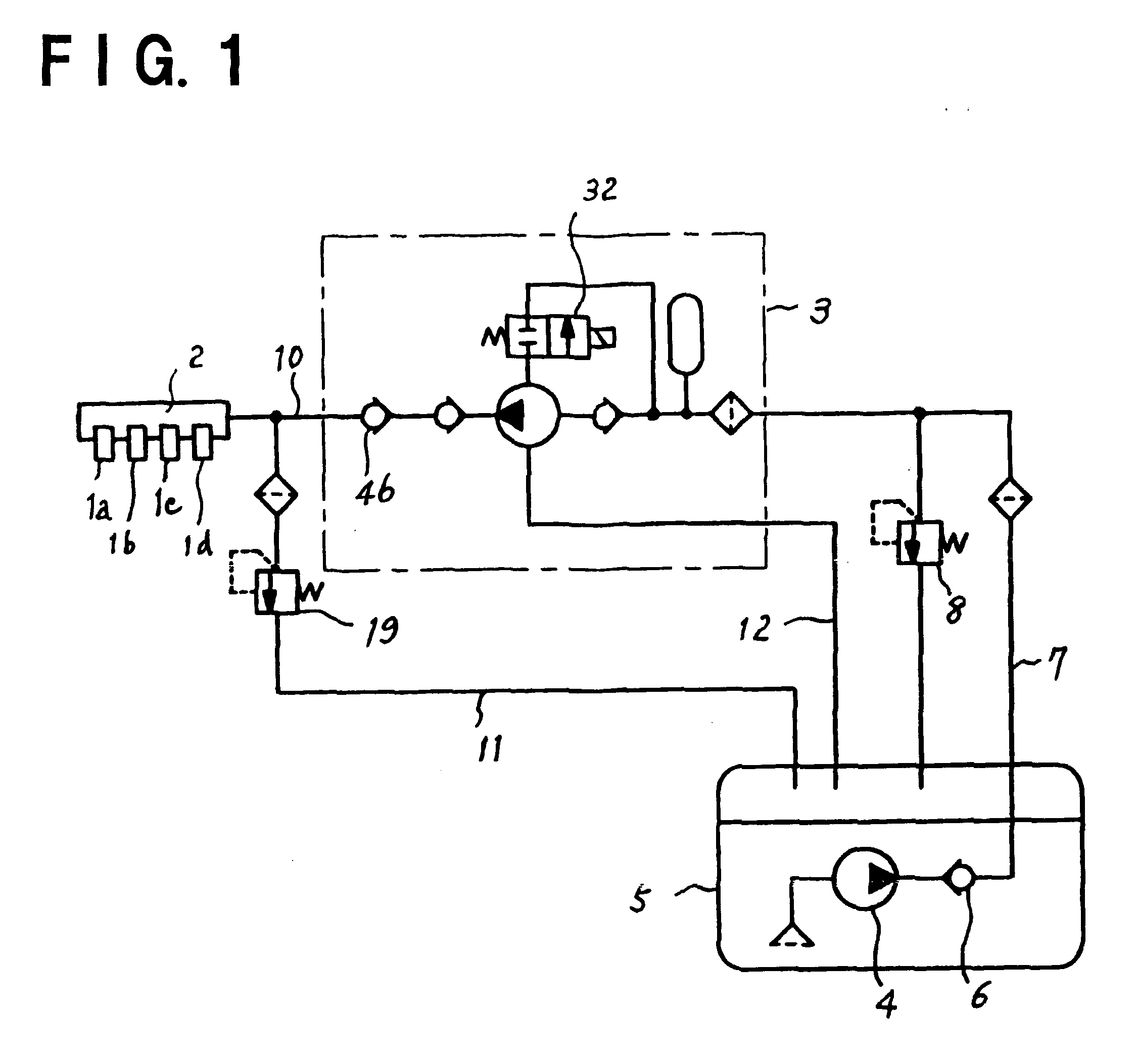
In FIG. 1, reference numerals 1a through 1d designate fuel injection valves for injecting fuel to the respective cylinders in an internal combustion engine, numeral 2 designates a delivery pipe which receives pressurized fuel and supplies the fuel to the fuel injection valves 1a-1d, numeral 3 a fuel pump for supplying pressurized fuel into the delivery pipe 2 through a fuel passage 10, numeral 4 a low pressure pump for supplying fuel from a fuel tank 5 through a fuel passage 7 to the fuel pump 3, numeral 6 a check valve provided in the fuel passage 7 to prevent fuel from flowing in a reverse direction, numeral 8 a low pressure regulator for controlling a pressure in the fuel passage 7, numeral 12 a return passage to return fuel from the fuel pump 3 to the fuel tank 5, and numeral 19 a high pressure regulator which is located in a high-pressure fuel passage such as the delivery pipe 2 and the fuel passage 10 and is so adapted as to relieve fuel to the fuel tank 5 through a fuel passa...

embodiment 2

The variable delivery fuel supply device according to a second embodiment of the present invention will be described with reference to FIGS. 4 to 6 wherein the same reference numerals designate the same or corresponding parts.

The construction of the second embodiment is the same as that of the first embodiment shown in FIG. 1 except that the high pressure regulator 19 is assembled integrally with the fuel pump 3 wherein FIG. 4 shows that the high pressure regulator 19 is depicted in a frame showing the fuel pump 3.

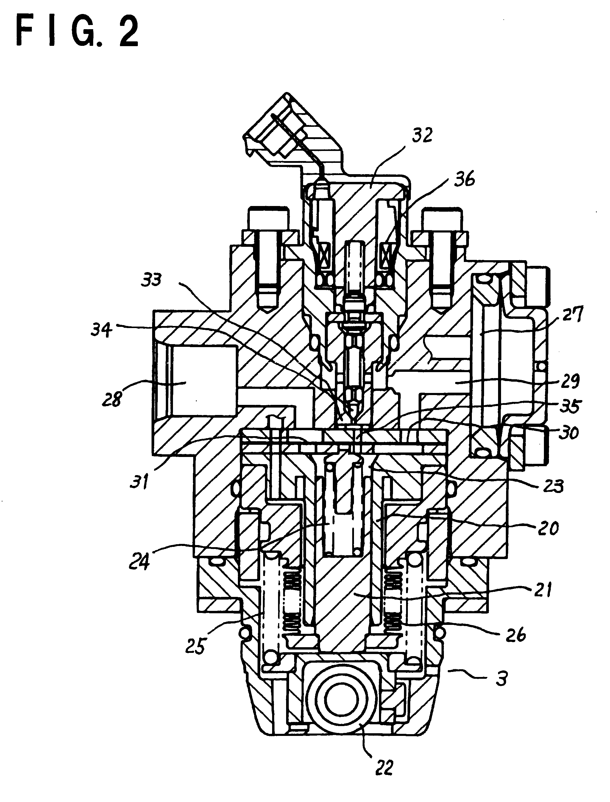
In the fuel pump 3 shown in FIG. 5, reference numeral 20 designates a cylinder, numeral 21 a plunger 21, numeral 22 a roller, numeral 23 a pressurizing chamber, numeral 24 a spring for urging the plunger, numeral 25 a spring for urging the roller 22, and numeral 26 a bellows made of metal. These structural elements are the same as those of the first embodiment shown in FIG. 2. Numeral 27 designates a fuel intake port through which fuel is supplied from the fuel tank 5, and...


PUM


Abstract

A variable delivery fuel supply device capable of obtaining a stable fuel pressure even in a case of inoperability of an electromagnetic valve and capable of improving the durability of the electromagnetic valve, which comprises fuel injection valves 1a through 1d for injecting fuel to respective cylinders of an internal combustion engine, a delivery pipe 2 connected with the fuel injection valves 1a through 1d, a fuel pump 3 which sucks fuel from a fuel intake valve into a pressurizing chamber 23 by a reciprocating action of a plunger 21 in a cylinder 20 and supplies the pressurized fuel into the delivery pipe 2 through a discharge valve 31, an electromagnetic valve 32 located in a relief passage 35 communicating the pressurizing chamber 23 of the fuel pump 32 with the fuel intake port 27 and is adapted to control a discharge quantity of the pressurized fuel by relieving the pressurized fuel in the pressurizing chamber 23 into the fuel intake port 27 at the time of opening the valve to thereby control a fuel pressure in the delivery pipe 2, and a high pressure regulator 19 for controlling a fuel pressure by relieving the pressurized fuel in a high-pressure fuel passage including the delivery pipe 2.

Description

1. Field of the InventionThe present invention relates to a variable delivery fuel supply device which is used for an internal combustion engine for automobiles, in particular, for a cylinder injection type gasoline engine requiring highly pressurized fuel and which is capable of controlling an amount of fuel to be supplied to fuel injection valves.2. Discussion of BackgroundFIG. 7 is a systematic diagram showing the construction of a conventional variable delivery fuel supply device, and FIG. 8 is a cross-sectional view of a relief valve used for the conventional delivery fuel supply device.The systematic diagram of FIG. 7 is disclosed, for instance, in JP-A-11-200990. In FIG. 7, reference numerals 1a through 1d designate fuel injection valves for injecting fuel into respective cylinders of an internal combustion engine, numeral 2 designates a delivery pipe for supplying fuel to the fuel injection valves, numeral 3 a fuel pump for supplying pressurized fuel to the delivery pipe 2, ...

Claims


Application Information

Patent Timeline
IPC IPC(8): F02M63/00F02M63/02F04B49/22F04B49/08F04B49/24F02M55/04F02M55/00F02M69/00F02D41/02F02D41/04F02D41/22F02M47/00F02M51/02F02M55/02
CPCF02M63/0225F04B49/08F04B49/24F02M55/04F02M2200/315F02M2200/40
Inventor ONISHI, YOSHIHIKOMIYAJIMA, MASAYASU
Owner MITSUBISHI ELECTRIC CORP
Why Eureka
Try Eureka