Universal reflow fixture

a universal reflow and fixture technology, applied in the direction of workpiece holders, manufacturing tools, solventing apparatus, etc., can solve the problems of reducing the registration between features, introducing additional costs, and increasing the difficulty of steps

Inactive Publication Date: 2001-04-03
CHUNG HENRY
View PDF7 Cites 30 Cited by
  • Summary
  • Abstract
  • Description
  • Claims
  • Application Information

AI Technical Summary

Benefits of technology

minimizing heat loss due to conduction of heat into the fixture during the reflow step;
minimizing the amount of stretch of the stencil during the stencil printing step;
permitting that the board be positionable under a pick and place head by simply sliding the board without a requirement to first move the head away from the plane of the board in order to avoid interference with the frame,
Supporting contact at the edges of the board are made by a scallop pattern on the inside edge of the frame so that contact by the frame to the edge of the board is a plurality of narrow line edges wherein each edge has a very small area of contact with the board thereby providing negligible loss of heat by conduction from the board.
The fixture is machined from sheets of a fiberglass composition found by the inventor to be particularly effective in resisting warpage and degradation such as encountered in solder reflow operations.

Problems solved by technology

This frequent transfer from one fixture to another is time consuming, subject to accidents or misalignments causing errors, introduces additional costs in terms of a requirement to provide more fixtures, provide storage space and accounting activity to keep track of the fixtures.
This step is made even more difficult when pressure is applied to the screen which stretches the screen each time the screen is used.
Eventually the screen becomes permanently stretched so that registration between features is diminished leading to inaccuracies.
Another important expense is the requirement to have various sizes of fixturess--each size matching a size requirement for a board.
None of these inventions disclose a single board that addresses all of the problems discussed above.

Method used


Image

  • Universal reflow fixture
  • Universal reflow fixture
  • Universal reflow fixture

Examples


Embodiment Construction

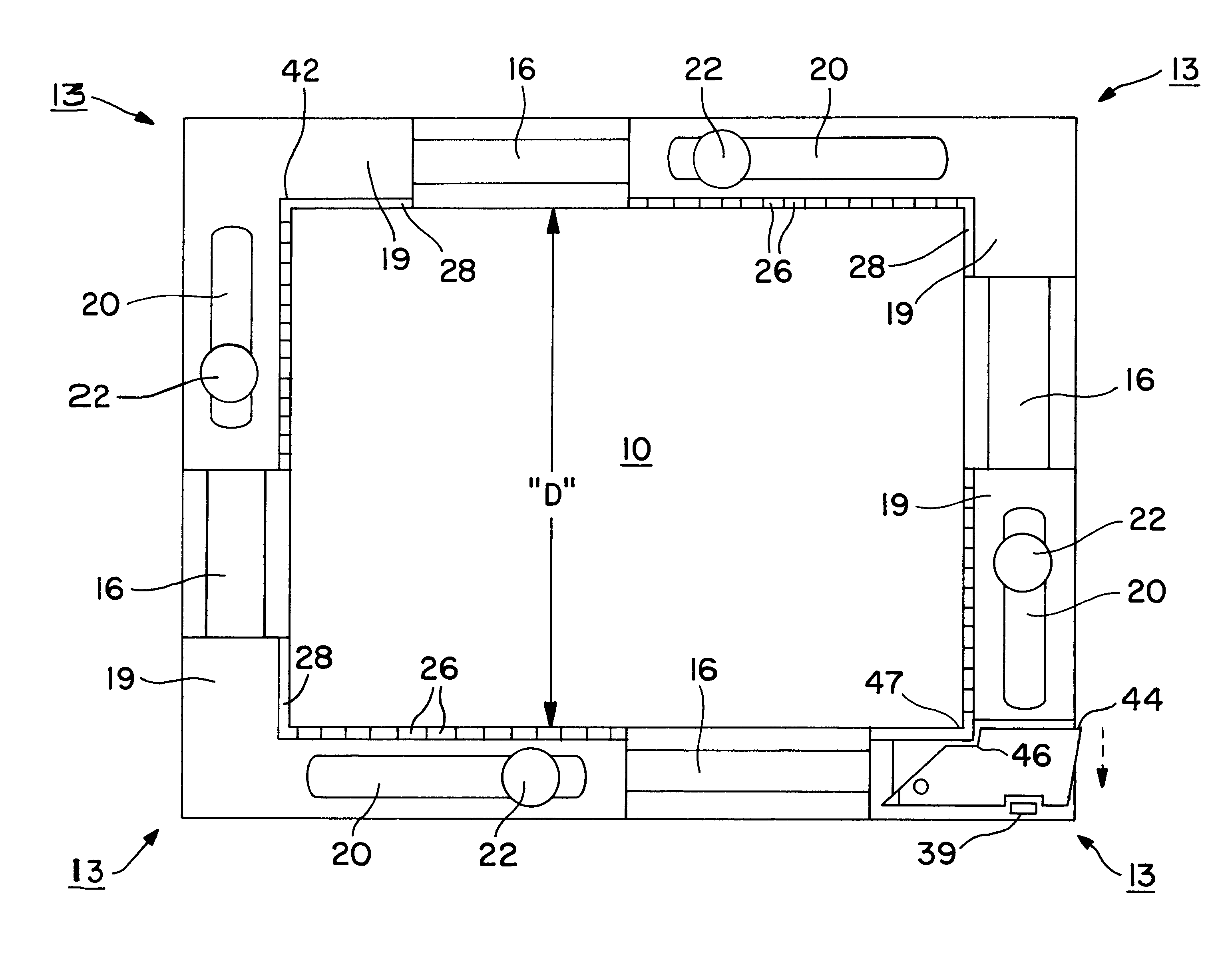
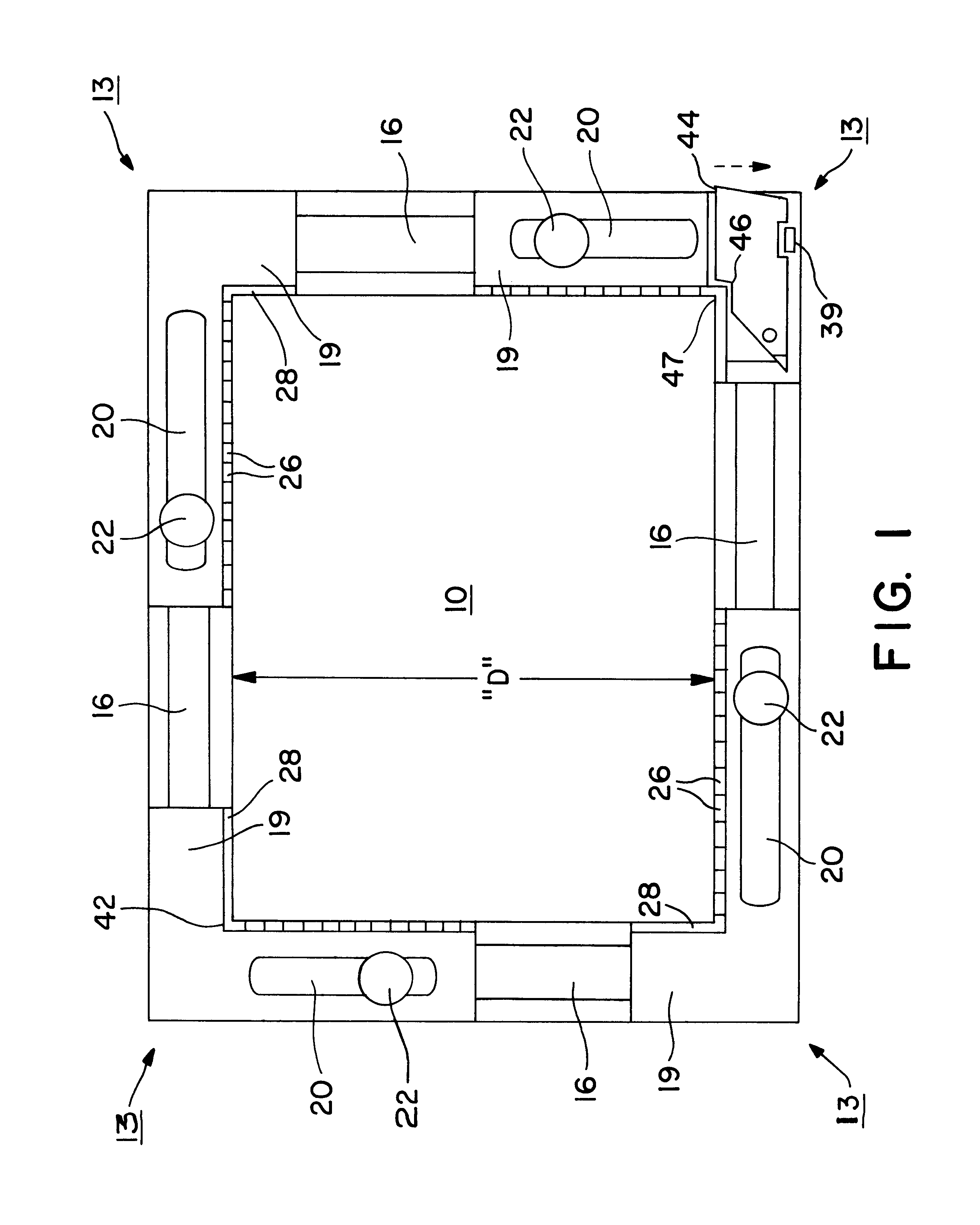
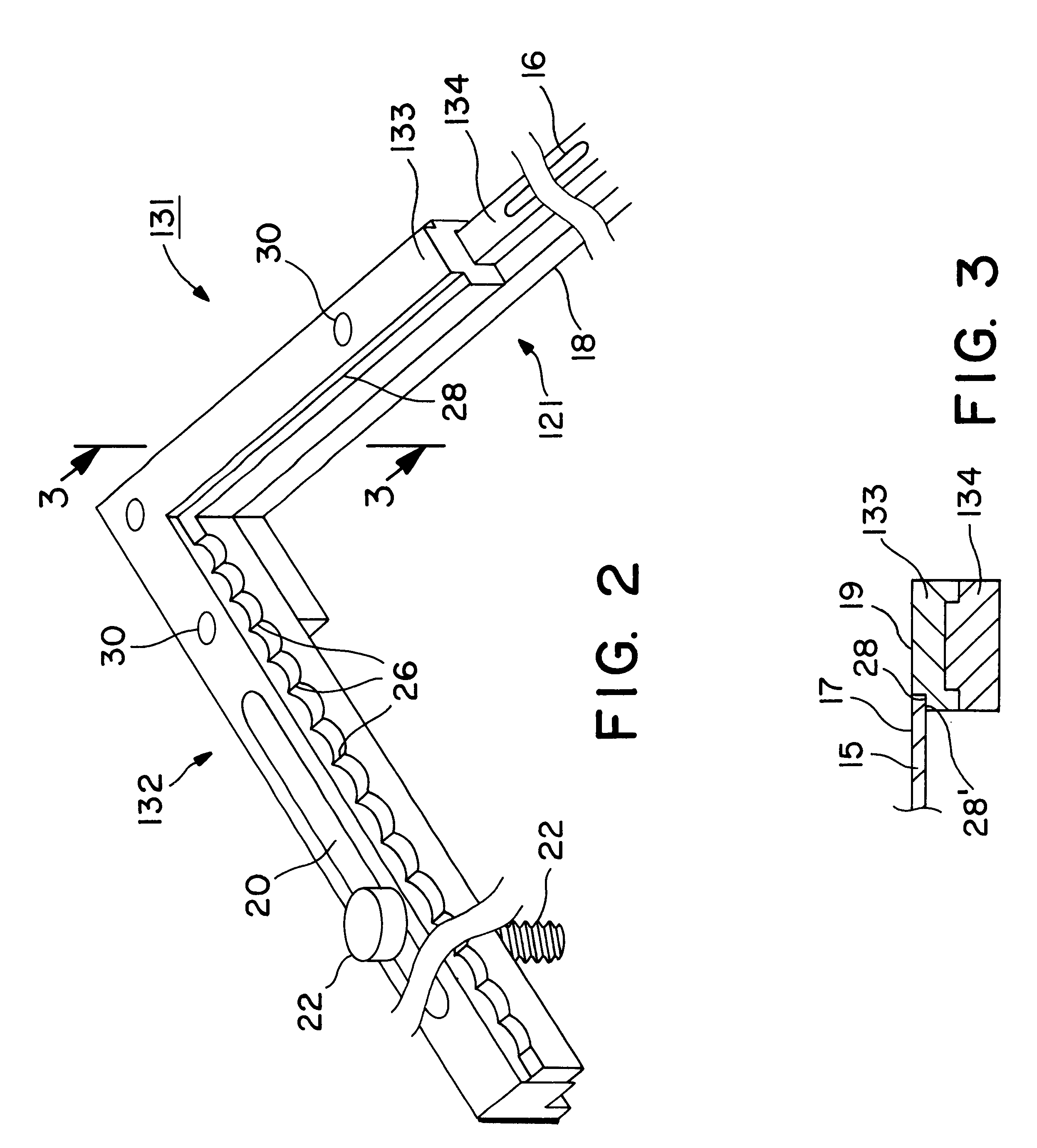
Turning now to a discussion of the drawings, FIG. 1 shows the plan surface of the assembled frame according to one embodiment of this invention. The frame comprises four rigid identical angles 13. Each angle 13 is shown in greater detail in the perspective view of FIG. 2. Each angle has a first leg 131 joined at one end to an end of the second leg 132. Leg 132 has an elongated groove 14 that slideably engages the tongue 16 on the extended end 18 of leg 131 of the adjoining angle 13. Leg 132 also has a slot 20 through which a set screw 22 is positioned and screwed into a threaded hole 24 in leg 131 of the neighboring angle 13. This feature permits adjusting the size"D" of the frame opening by sliding legs 131 over legs 132 and then clamping the legs in position by tightening set screws 22.

While the angles shown in the example of FIG. 1 are equal so that the four joined angles form a square, it will be understood that the lengths of the legs of tha angles may be selected to form a rec...


PUM


Abstract

A frame comprising four angles each angle having two legs, each leg connected to a a leg of a neighboring angle wherein locations of attachment of the legs are adjustable so as to accommodate a range of sizes of boards for a surface mount manufacturing process. One leg of each angle has a tongue and the other leg has a groove so that tongue of one leg slideably engages the groove of the leg of a neighboring angle to enable adjustment in size of the frame opening. The board is supported on a shoulder around the frame opening with the surface of the board opposite the supporting shoulder surface coplanar with the plane surface of the frame. A flat spring loaded rotatable finger on the plan surface in one corner of the board urges the board toward the opposite corner of the frame.

Description

This invention relates to apparatus for assembling components on printed circuit boards (PCB) and particularly to a fixture that supports the board through manufacturing steps including soldering.BACKGROUND AND INFORMATION DISCLOSUREThe technology for manufacturing circuits comprising components mounted on printed circuit boards has evolved continuously during the past fifty years keeping pace with the evolution of discrete semiconductor devices to present high density integrated circuits on a chip.The first boards were simply plastic phenolic boards with printed wiring to which discrete components were hand soldered. As chips holding integrated circuits were developed, the technology of "plated-through-holes technology appeared.The dip is a chip imbedded in a plastic block enclosure generally about the size of a postage stamp. The block also contains leads extending from contact with the chip to outside the block so that the integrated circuit resembled a centipede including the bl...

Claims


Application Information

Patent Timeline
Patent Type & Authority Patents(United States)
IPC IPC(8): B23K3/08B25B5/14B23K3/00B25B5/00
CPCB23K3/087B25B5/142B23K2201/42Y10S269/903B23K2101/42
Inventor CHUNG, HENRY
Owner CHUNG HENRY
Why Eureka
Try Eureka